Poradnik: Rysunek Roboczy kształt z tekstu
| Temat |
|---|
| Projekt produktu |
| Poziom trudności |
| początkujący |
| Czas wykonania |
| 30 minut |
| Autorzy |
| r-frank oraz vocx |
| Wersja FreeCAD |
| 0.17 i nowszy |
| Pliki z przykładami |
| Draft_Shapestring_Text |
| Zobacz również |
| - |
Wprowadzenie
Ten poradnik został pierwotnie napisany przez Rolanda Franka (†2017, r-frank), a następnie przepisany i zilustrowany przez vocx.
Ten samouczek opisuje metodę tworzenia tekstu 3D i używania go z obiektami bryłowymi w środowiska Część. Omówimy jak
- wstawiać obrysowany tekst za pomocą narzędzia
kształt z tekstu,
- wyciągnięcie go do postaci bryły 3D za pomocą narzędzia
Wyciągnij,
- pozycjonować go w przestrzeni 3D za pomocą umiejscowienia, oraz
przesunięcie (używa szkicu jako geometrii pomocniczej), oraz
- wygrawerować tekst poprzez zastosowanie funkcji logicznej
Wytnij.
Aby użyć funkcji Kształt z tekstu wewnątrz środowiska pracy Projekt Części, proces jest zasadniczo taki sam jak w przypadku środowiska pracy Część, ale Kształt z tekstu jest umieszczany wewnątrz Zawartości środowiska Projekt Części w celu jego wyciągnięcia. Przejdź do końca tego samouczka, aby uzyskać więcej informacji.
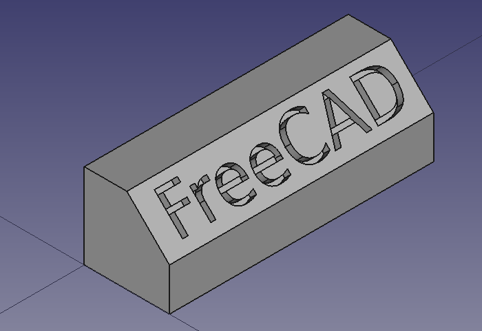
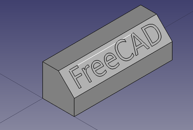
Ostateczny model wygrawerowanego tekstu.
Środowisko pracy Szkicownik jest krótko używane do narysowania linii pomocniczej. Więcej informacji o narzędziach tego środowiska pracy można znaleźć na stronach:
Sposób postępowania
1. Otwórz FreeCAD, utwórz nowy pusty dokument za pomocą Plik → Nowy i przejdź do środowiska pracy Część.
- 1.1. Naciśnij przycisk
Widok izometryczny lub naciśnij 0 na klawiaturze numerycznej, aby zmienić widok na izometryczny w celu lepszej wizualizacji brył 3D.
- 1.2. Naciśnij przycisk
Dopasuj wszystko za każdym razem, gdy dodajesz obiekty, aby przesuwać i powiększać widok 3D tak, aby wszystkie elementy były widoczne w widoku.
- 1.3. Przytrzymaj Ctrl podczas klikania, aby zaznaczyć wiele elementów. Jeśli wybrałeś coś źle lub chcesz usunąć zaznaczenie, kliknij na puste miejsce w oknie widoku 3D.
Utwórz kształt podstawowy
2. Wstaw prostopadłościan, klikając Sześcian.
- 2.1. Wybierz obiekt
Sześcianw widoku drzewa. - 2.2. Zmień wymiary w zakładce Dane edytora właściwości.
- 2.3. Zmień wartość Szerokość na
31 mm.
3. Create a chamfer.
- 3.1. Select the upper edge (
Edge6) on the front face of theCubein the 3D view. - 3.2. Press
Chamfer.
- 3.3. In the Chamfer edges task panel go to Selection, choose Select edges. As Chamfer type choose
Equal distance, then set Length to5 mm. - 3.4. Press OK. This will create a
Chamferobject. - 3.5. In the tree view, select
Chamfer, in the View tab change the value of Line Width to2.0.
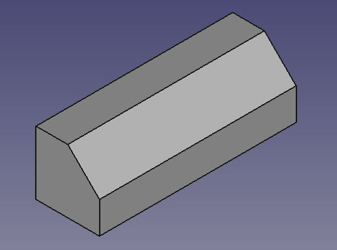
Base object created from a cube and a chamfer operation.
Insert the ShapeString
4. Switch to the Draft Workbench.
- 4.1. Make sure nothing is selected in the tree view.
- 4.2. Establish the working plane to XY (Top) by clicking on
SelectPlane and pressing
Top (XY).
5. Insert the text "FreeCAD".
- 5.1. Click on
ShapeString.
- 5.2. Change X to
0 mm. - 5.3. Change Y to
0 mm. - 5.4. Change Z to
0 mm. - 5.5. Or press Reset point.
- 5.6. Change String to
FreeCAD; change Height to5 mm; change Tracking to0 mm. - 5.7. Make sure Font file points to a valid font, for example,
/usr/share/fonts/truetype/dejavu/DejaVuSans.ttf. Press the ellipsis ... to open the operating system's dialog to find a font.- Note: for more details about working with fonts please refer to the Draft ShapeString Notes section.
- 5.8. Press OK. This will create a
ShapeStringobject. - 5.9. Recompute the document by pressing
Refresh.
- 5.10. In the tree view, select
ShapeString, in the View tab change the value of Line Width to2.0. - 5.11. In the tree view, select
Chamfer, in the View tab change the value of Visibility tofalse, or press Space in the keyboard. This will hide the object, so you can see theShapeStringbetter. - 5.12. To see the ShapeString from above change the view by pressing
Top (XY), or 2 in the keyboard.
- 5.13. To restore the view to isometric, press
View isometric, or 0 in the keyboard.
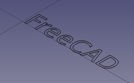
Text created as a ShapeString, that is, as a collection of edges in a plane.
Create the solid 3D text
6. Switch back to the Part Workbench.
- 6.1. In the tree view, select
ShapeString, then pressExtrude.
- 6.2. In the Extrude task panel go to Direction, choose Along normal; in Length, set Along to
1 mm; also tick the Create solid option. - 6.3. Press OK. This will create an
Extrudeobject. - 6.4. In the tree view, select
Extrude, in the View tab change the value of Line Width to2.0.
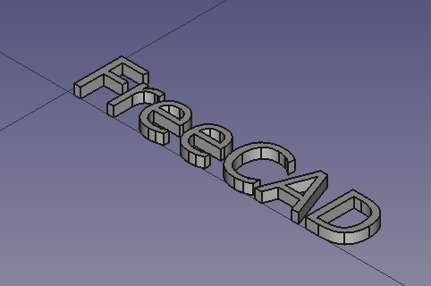
Text created as a ShapeString, and turned into a solid by extrusion.
Insert auxiliary sketch for positioning
Now we will draw a simple sketch that will be used as auxiliary geometry to position the ShapeString extrusion.
7. In the tree view, select Extrude, and press Space in the keyboard to make it invisible.
8. Switch to the Sketcher Workbench.
9. In the tree view, select Chamfer, and press Space in the keyboard to make it visible.
- 9.1. Choose the sloped face created by the chamfer operation (
Face3). - 9.2. Click on
NewSketch. In the Sketch attachment dialog, select
FlatFace, and press OK. - 9.3. The view should adjust automatically so that the camera is parallel to the selected face.
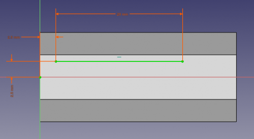
- 9.4. Draw a horizontal line in a general position on top of the face. The length is not important; we are just interested in its position.
- 9.5. Constrain the left endpoint to be
2.5 mmaway from the local X axis and from the local Y axis, usingConstrainDistanceX and
ConstrainDistanceY.
- 9.6. Since the sketch is just an auxiliary object, we don't need to have it fully constrained. You can do this if you wish by assigning a fixed distance, say,
20 mm, again withConstrainDistanceX.
- 9.7. Close the sketch.
Line being created with the sketcher, with constraints.
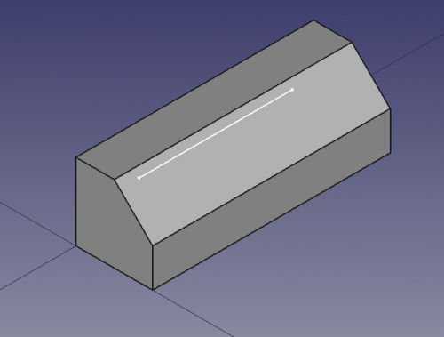
Sketch line created on top of the solid face, to be used as reference guide for positioning the extruded text.
Positioning the solid text in 3D space
10. In the tree view, select Extrude, and press Space in the keyboard to make it visible.
11. With Extrude still selected, in the Data tab of the property editor, click on the Placement value so the ellipsis button ... appears on the right and click on that button.
- 11.1. Tick the option Apply incremental changes.
- 11.2. Change the Rotation to
Rotation axis with angle; Axis toZ(by setting theX,YandZvalues of the axis inputboxes to0,0and1respectively,Zis the third inputbox), and Angle to90 deg, then click on Apply. This will apply a rotation around the Z-axis, and will reset the Angle field to zero. - 11.3. Change the Rotation to
Rotation axis with angle; Axis toY(by setting theX,YandZvalues of the axis inputboxes to0,1and0respectively), and Angle to45 deg, then click on Apply. This will apply a rotation around the Y-axis, and will reset the Angle field to zero. - 11.4. Click on OK to close the dialog.
12. Switch again to the Draft Workbench.
- 12.1. Switch to "Wireframe" draw style with View → Draw style →
Wireframe, or press the
Wireframe button in the view toolbar. This will allow you to see the objects behind other objects.
- 12.2. Make sure the Draft Snap "Snap to endpoint" method is active. This can be done from the menu Draft → Snapping →
Toggle On/Off, and then →
Endpoint, or by pressing the
ToggleSnap and
Snap endpoint buttons in the Snap toolbar.
13. In the tree view, select Extrude.
- 13.1. Click on
Move.
- 13.2. In the 3D view click on the upper left corner point of the
Extrudeobject (1), and then click on the leftmost point in the line drawn with the sketcher (2). - 13.3. If
Snap endpoint is active, as soon as you move the pointer close to a vertex, you should see that it attaches to it exactly.
- Note: if you have problems snapping to vertices, make sure only the
Snap endpoint method is enabled. Having multiple snapping methods active at the same time may make it difficult to select the right feature.
- 13.4. The extruded text should now be inside the body of the
Chamferobject.
The extruded ShapeString should be moved to the position of the sketched line that lies on the face of the base body.
Extruded ShapeString positioned in the Chamfer.
Creating engraved text
14. Switch back to the Part Workbench.
- 14.1. Switch to "As is" draw style with View → Draw style →
As is, or press the
As is button in the view toolbar. This will show all objects with the normal shading and color.
- 14.2. In the tree view, select
Sketch, and press Space in the keyboard to make it invisible.
15. In the tree view select Chamfer first, and then Extrude.
- 15.1. Then press
Cut. This will create a
Cutobject. This is the final object. - Note: the order in which you select the objects is important for the cut operation. The base object is selected first, and the subtracting object comes at the end.
- 15.2. In the tree view, select
Cut, in the View tab change the value of Line Width to2.0.
Final model of a filleted cube, with carved text created from a ShapeString, Extrude, and boolean Cut operations.
Engraving 3D text with the PartDesign Workbench
A similar process as described above can be done with the PartDesign Workbench.
- Create the
Draft ShapeString first.
- Create a
PartDesign Body, make it active, and add a base solid by adding primitives, or using a Sketch and extruding it with
PartDesign Pad.
- Move the
ShapeStringobject into the active body. - Attach the
ShapeStringobject to one of the faces of the solid, or to aPartDesign Plane, using
Part EditAttachment.
- Now create a
PartDesign Pad or a
PartDesign Pocket from the
ShapeString, in order to produce an additive or a subtractive feature of the base body, respectively.
See the forum thread, How to use ShapeStrings in PartDesign.
Notes
- To create curved text you can use
 Macro FCCircularText.
 - To import text from an SVG file look at the Import text and geometry from Inkscape tutorial.
- Bryły pierwotne: Prostopadłościan, Walec, Sfera, Stożek, Torus, Rura, Bryły pierwotne, Konstruktor kształtu
- Tworzenie i modyfikacja: Wyciągnij, Wyciągnij przez obrót, Odbicie lustrzane, Zaokrąglenie, Fazka, Utwórz ścianę z linii łamanych, Powierzchnia prostokreślna, Wyciągnięcie przez profile, Wyciągnięcie po ścieżce, Przecięcie, Przekrój poprzeczny, Odsunięcie 3D, Odsunięcie 2D, Grubość, Rzutowanie na powierzchnię, Mocowanie
- Funkcje logiczne: Utwórz złożenie, Rozbij złożenie, Filtr złożeń, Funkcje logiczne, Wytnij, Połączenie, Część wspólna, Przyłącz, Dołącz do osadzenia, Wycięcie połączenia, Funkcja logiczna rozdzielająca, Pokrój część, Krojenie, XOR
- Wymiarowanie: Wymiarowanie liniowe, Wymiarowanie kątowe, Odśwież wymiary, Usuń wymiary, Przełącz widoczność wymiaru, Przełącz widoczność wymiarów przestrzennych, Przełącz widoczność wymiarów przyrostowych
- Narzędzia struktury: Część, Grupa
- Narzędzia wspomagające: Utwórz zawartość, Nowy szkic, Edycja szkicu, Mapuj szkic na ścianę
- Narzędzia do modelowania
- Narzędzia do ustalania położenia punktów odniesienia: Utwórz punkt odniesienia, Utwórz linię odniesienia, Utwórz płaszczyznę odniesienia, Układ współrzędnych, Łącznik kształtu, Łącznik kształtów podrzędnych, Utwórz klon
- Narzędzia addytywne: Wyciągnięcie, Wyciągnij przez obrót, Wyciągnięcie przez profile, Wyciągnięcie po ścieżce, Addytywna helisa, Addytywny sześcian, Addytywny walec,Addytywna sfera, Addytywny stożek, Addytywna elipsoida, Addytywny torus, Addytywny graniastosłup, Addytywny klin
- Narzędzia subtraktywne: Kieszeń, Otwór, Rowek, Subtraktywne wyciągnięcie przez profile, Subtraktywne wyciągnięcie po ścieżce, Subtraktywna helisa, Subtraktywny sześcian, Subtraktywny walec, Subtraktywna sfera, Subtraktywny stożek, Subtraktywna elipsoida, Subtraktywny torus,Subtraktywny graniastosłup, Subtraktywny klin
- Narzędzia do transformacji: Odbicie lustrzane, Szyk liniowy, Szyk kołowy, Transformacja wielokrotna, Skaluj
- Narzędzia ulepszające: Zaokrąglenie, Fazka, Pochylenie ścian, Grubość
- Funkcje logiczne Funkcje logiczne
- Dodatki: Przenieś, Koło łańcuchowe, Koło zębate ewolwentowe, Kreator projektowania wału
- Narzędzia menu kontekstowego: Ustaw czubek, Przenieś cechę, Przenieś cechę w drzewie, Wygląd zewnętrzny, Ustaw kolor
- Przybory: Nowy szkic, Edycja szkicu, Mapuj szkic na powierzchnię, Zmień orientację szkicu, Sprawdź poprawność szkicu, Połącz szkice, Odbicie lustrzane szkicu, Zamknij szkic, Widok szkicu, Widok przekroju, Włącz / wyłącz siatkę, Włącz / wyłącz przyciąganie, Kolejność renderowania, Przerwij operację
- Geometrie szkicownika: Punkt, Linia, Komponent utwórz łuk, Łuk, Utwórz łuk przez 3 punkty, Komponent utwórz okrąg, Okrąg, Utwórz okrąg przez 3 punkty, Komponent utwórz stożek, Utwórz elipsę względem środka, Utwórz elipsę przez 3 punkty, Utwórz łuk elipsy, Utwórz łuk hyperboli, Utwórz łuk paraboli, Komponent utwórz krzywą złożoną, Utwórz krzywą złożoną, Utwórz okresową utwórz krzywą złożoną, Polylinia (linia wielopunktowa), Prostokąt, Komponent utwórz wielokąt foremny, Trójkąt, Kwadrat, Pięciokąt, Sześciokąt, Siedmiokąt, Ośmiokąt, Utwórz wielokąt foremny, Rowek, Zaokrąglenie, Zaokrąglenie z zachowaniem wiązań, Przytnij, Rozszerz, Geometria zewnętrzna, Kalka techniczna, Tryb konstrukcyjny
- Wiązania szkicownika
- Wiązania geometryczne Wiązanie zbieżności punktów, Wiązanie punktu na obiekcie, Wiązanie pionowe, Wiązanie poziome, Wiązanie równoległości, Wiązanie prostopadłości, Wiązanie styczności, Wiązanie równości, Wiązanie symetrii, Wiązanie zablokowania
- Wiązania wymiarów Wiązanie blokady odległości, Zwiąż odległość poziomą, Zwiąż odległość pionową, Wiązanie odległości, Wiązanie promienia, Wiązanie średnicy, Zwiąż automatycznie promień / średnicę, Wiązanie kąta, Wiązanie prawo Snella
- Narzędzia wiązań: Przełącz kontrolę wiązania, Przełącz aktywność wiązania
- Narzędzia szkicownika Wybierz elementy bez wiązań, Wybierz powiązane więzy, Wybierz powiązaną geometrię, Wybierz zbędne wiązania, Wybierz wiązania konfliktowe, Pokaż / ukryj geometrię wewnętrzną, Wybierz odniesienie położenia, Wybierz oś poziomą, Wybierz oś pionową, Odbicie lustrzane, Klonuj, Kopiuj, Przesuń, Szyk prostokątny, Usuń wyrównanie osi, Usuń wszystkie geometrie, Usuń wszystkie wiązania
- Narzędzia B-spline dla szkicownika. Pokaż / ukryj stopień krzywej złożonej, Pokaż/ukryj ramkę kontrolną krzywej złożonej, Pokaż / ukryj grzebień krzywizny krzywej złożonej, Pokaż / ukryj wyświetlanie węzłów krzywej złożonej, Pokaż / ukryj wagę punktu kontrolnego krzywej złożonej, Konwertuj geometrię na krzywą złożoną, Zwiększ stopień krzywej złożonej, Zmniejsz stopień krzywej złożonej, Zwiększ krotność węzłów krzywej złożonej, Zmniejsz krotność węzła krzywej złożonej, Wstaw węzeł, Połącz krzywe
- Przestrzeń wirtualna szkicownika Przełącz przestrzeń wirtualną
- Dodatkowe: Okienko dialogowe Szkicownika, Preferencje, Skrypty Szkicownika
- Jak zacząć
- Instalacja: Pobieranie programu, Windows, Linux, Mac, Dodatkowych komponentów, Docker, AppImage, Ubuntu Snap
- Podstawy: Informacje na temat FreeCAD, Interfejs użytkownika, Profil nawigacji myszką, Metody wyboru, Nazwa obiektu, Edytor ustawień, Środowiska pracy, Struktura dokumentu, Właściwości, Pomóż w rozwoju FreeCAD, Dotacje
- Pomoc: Poradniki, Wideo poradniki
- Środowiska pracy: Strona Startowa, Architektura, Assembly, CAM, Rysunek Roboczy, MES, Inspekcja, Siatka, OpenSCAD, Część, Projekt Części, Punkty, Inżynieria Wsteczna, Robot, Szkicownik, Arkusz Kalkulacyjny, Powierzchnia 3D, Rysunek Techniczny, Test Framework
