Tutorial custom placing of windows and doors/pl: Difference between revisions
(Created page with "{{Caption|align=center|Nazwane wiązania szkicu, które można modyfikować bez wchodzenia do szkicu.}}") |
(Created page with "11. Wróć do środowiska pracy Architektura i po wybraniu nowego {{Incode|Sketch002}} użyj narzędzia Okno. Okno zostanie utworzone i zrobi dziurę w ścianie. Okno zostało utworzone z niestandardowego szkicu, a nie z ustawienia wstępnego, więc należy je edytować, aby poprawnie wyświetlić jego komponenty, czyli stałą ramę, wewnętrzną ramę i szklany panel.") |
||
| Line 120: | Line 120: | ||
{{Caption|align=center|Nazwane wiązania szkicu, które można modyfikować bez wchodzenia do szkicu.}} |
{{Caption|align=center|Nazwane wiązania szkicu, które można modyfikować bez wchodzenia do szkicu.}} |
||
11. Wróć do środowiska pracy [[Arch_Workbench/pl|Architektura]] i po wybraniu nowego {{Incode|Sketch002}} użyj narzędzia [[Arch_Window/pl|Okno]]. Okno zostanie utworzone i zrobi dziurę w ścianie. Okno zostało utworzone z niestandardowego szkicu, a nie z ustawienia wstępnego, więc należy je edytować, aby poprawnie wyświetlić jego komponenty, czyli stałą ramę, wewnętrzną ramę i szklany panel. |
|||
11. Change back to the [[Arch Workbench]] and, with the new {{incode|Sketch002}} selected, use [[Arch Window]]. A window will be created, and will make a hole in the wall. The window is made from a custom sketch, and not from a preset, so it needs to be edited in order to correctly display its components, that is, the fixed frame, the inner frame, and the glass panel. |
|||
[[Image:08_T02_window_basic_in_wall.png|600px|center]] |
[[Image:08_T02_window_basic_in_wall.png|600px|center]] |
||
Revision as of 19:44, 9 March 2024
| Temat |
|---|
| Architektura |
| Poziom trudności |
| średnio zaawansowany |
| Czas wykonania |
| 60 minut |
| Autorzy |
| vocx |
| Wersja FreeCAD |
| 0.18 lub nowszy |
| Pliki z przykładami |
| nie dołączono |
| Zobacz również |
| - |
Wprowadzenie
Ten poradnik pokazuje, jak umieścić niestandardowe okno i drzwi w modelu budynku. Wykorzystuje on środowisko Rysunek Roboczy, Architektura i Szkicownik.
Często używanymi narzędziami są: siatka, narzędzia przyciągania, polilinia, ściana, okno i Utwórz szkic. Użytkownik powinien być zaznajomiony z tworzeniem szkiców z wiązaniami.
Ten poradnik został zainspirowany poradnikami autorstwa jpg87 opublikowanymi na forum FreeCAD.
Zobacz także poniższy wątek, aby uzyskać więcej informacji na temat położenia okien i drzwi.
Zobacz także poniższą stronę, aby zobaczyć kilka filmów na temat wyrównywania okien.
Konfiguracja
1. Otwórz program FreeCAD, utwórz nowy pusty dokument i przejdź do środowiska Architektura.
2. Upewnij się, że jednostki są prawidłowo ustawione w menu Edycja → Preferencje ... → Ogólne → Jednostki. Na przykład MKS (m/kg/s/stopnie) jest dobre do radzenia sobie z odległościami w typowym budynku; co więcej, ustaw liczbę miejsc dziesiętnych na 4, aby uwzględnić nawet najmniejsze ułamki metra.
3. Użyj przycisku Przełącz widoczność siatki, aby wyświetlić siatkę z wystarczającą rozdzielczością. Wygląd siatki można dostosować w menu Edycja → Preferencje → Rysunek Roboczy → Siatka i przyciąganie → Siatka. Ustaw linie co 50 mm, z głównymi liniami co 20 linii (co metr) i 1000 linii w sumie (siatka obejmuje obszar 50 m x 50 m).
4. Oddal widok 3D, jeśli znajdujesz się zbyt blisko siatki.
Teraz możemy stworzyć prostą ścianę, na której umieścimy okna i drzwi.
Umieszczenie ściany
5. Użyj narzędzia Polilinia, aby utworzyć linie. Idź w kierunku przeciwnym do ruchu wskazówek zegara.
- 5.1. Najpierw wskaż punkt (0, 4, 0); w oknie dialogowym wpisz 0 m Enter, 4 m Enter, 0 m Enter.
- 5.2. Drugi punkt w (2, 0, 0); w oknie dialogowym wpisz 2 m Enter, 0 m Enter, 0 m Enter.
- 5.3. Trzeci punkt w (4, 0, 0); w oknie dialogowym wpisz 4 m Enter, 0 m Enter, 0 m Enter.
- 5.4. Czwarty punkt w (6, 2, 0); w oknie dialogowym wpisz 6 m Enter, 2 m Enter, 0 m Enter.
- 5.4. Piąty punkt w (6, 5, 0); w oknie dialogowym wpisz 6 m Enter, 5 m Enter, 0 m Enter.
- 5.5. Na klawiaturze naciśnij A, aby zakończyć polilinię.
- 5.6. Na klawiaturze numerycznej naciśnij 0, aby uzyskać widok aksonometryczny modelu.
Upewnij się, że pole wyboru Względnie jest wyłączone, jeśli podajesz współrzędne bezwzględne. Uwaga 2: punkty mogą być również definiowane za pomocą kursora myszki poprzez wybranie przecięć na siatce, przy pomocy paska narzędzi przyciągania i metody Przyciągnij do siatki. Uwaga 3: można również tworzyć kształty programowo za pomocą skryptów w Python. Należy pamiętać, że większość funkcji oczekuje danych wejściowych w milimetrach.
import FreeCAD
import Draft

p = [FreeCAD.Vector(0.0, 4000.0, 0),
FreeCAD.Vector(2000.0, 0.0, 0.0),
FreeCAD.Vector(4000.0, 0.0, 0.0),
FreeCAD.Vector(6000.0, 2000.0, 0.0),
FreeCAD.Vector(6000.0, 5000.0, 0.0)]

w = Draft.makeWire(p, closed=False)
6. Wybierz DWire i kliknij narzędzie ściana. Ściana zostanie natychmiast utworzona z domyślną szerokością (grubością) 0,2 m i wysokością 3 m.
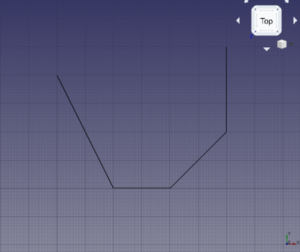
Linia bazowa dla ściany
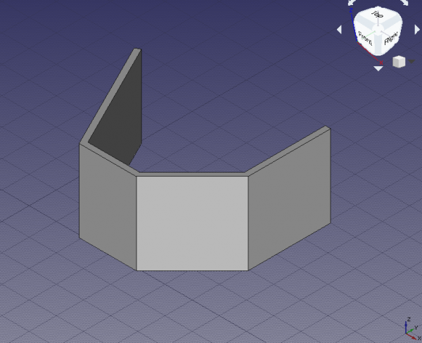
Ściana utworzona z polilini
Umieszczanie wstępnie ustawionych drzwi i okien
7. Kliknij narzędzie okno. Jako ustawienie wstępne wybierz Zwykłe drzwi i zmień wysokość na 2 m.
- 7.1. Zmień przyciąganie na Przyciągnij do punktu środkowego i spróbuj wybrać dolną krawędź ściany frontowej. W razie potrzeby ustaw widok standardowy, aby wybrać krawędź, a nie lico ściany; gdy punkt środkowy jest aktywny, kliknij, aby umieścić drzwi.
- 7.2. Kliknij ponownie narzędzie okno i umieść kolejne drzwi, ale tym razem w punkcie środkowym prawej ściany. Ustaw widok standardowy w razie potrzeby.
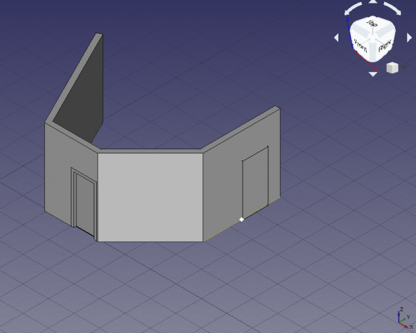
Przyciąganie do punktu środkowego dolnej krawędzi ściany w celu umieszczenia drzwi.
- Uwaga:
Wysokość parapetuto odległość od podłogi do dolnej krawędzi elementu. W przypadku drzwiWysokość parapetuwynosi zwykle 0 m, ponieważ drzwi zwykle dotykają podłog. Z drugiej strony okna mają zwykle odległość od 0,5 m do 1,5 m od podłogi.Wysokość parapetumożna ustawić tylko podczas początkowego tworzenia okna lub drzwi z ustawienia wstępnego. Po wstawieniu okna lub drzwi można zmodyfikować ich położenie, edytując wektor DANEPozycja[x, y, z]bazowego szkicu.
Tworzenie niestandardowych drzwi i okien
8. Przejdź do szkicownika. Wybierz część ściany po prawej stronie, która nie ma drzwi, kliknij na utwórz szkic. Wybierz Płaska ściana jako metodę mocowania. Jeśli istniejąca geometria zasłania widok, kliknij Widok przekroju, aby ją usunąć.
9. Narysuj efektowny szkic zawierający trzy zamknięte krzywe. Upewnij się, że nałożysz wiązania na wszystkie krzywe.
9.1. Zewnętrzna krzywa jest największa i definiuje główne wymiary obiektu okna oraz wielkość otworu tworzonego, gdy jest on osadzony w ścianie. Upewnij się, że wymiary są odpowiednio nazwane, na przykładSzerokośćiWysokość. Wiązanie również określa krzywiznę zewnętrznej krzywej. Nadaj mu odpowiednią nazwę, na przykładHeightCurve. 9.2. Druga krzywa jest przesunięta od zewnętrznej krzywej, i razem z nią definiują szerokość stałej ramy okna. Nazwij przesunięcie odpowiednio, na przykładFrameFixedOffset. Będzie ono używane zarówno do górnego pionowego, jak i poziomego przesunięcia. Dolne przesunięcie, jeśli ustawione na zero, spowoduje dotknięcie stałej ramy dolnej krawędzi okna. Można to wykorzystać do modelowania drzwi zamiast okna. Nadaj mu odpowiednią nazwę, na przykładFrameFixedBottom. 9.3. Trzecia, najbardziej wewnętrzna krzywa jest przesunięta od drugiej krzywej, i razem z nią definiują ramę okna, która może być otwierana. Najbardziej wewnętrzna krzywa również określa wielkość panelu szklanego. Ponownie, nadaj znaczące nazwy tym przesunięciom, na przykładFrameInnerOffsetiFrameInnerBottom. 9.4. Aby z powodzeniem zbudować szkic, użyj wiązań poziomych (Wiązanie poziome) i pionowych (Wiązanie pionowe) dla prostych boków; użyj pomocniczej geometrii konstrukcyjnej (Przełącz tryb konstrukcji), oraz wiązań styczności (Wiązanie styczności) do poprawnego umieszczenia łuków kołowych na górze. Ponieważ okno jest symetryczne, rozważ używanie wiązań równości (Wiązanie równości), symetrii (Wiązanie symetrii), oraz punktu na obiekcie (Zwiąż punkt na obiekcie) tam, gdzie to ma sens.

Wiązania dla zewnętrznych linii szkicu tworzących okno.
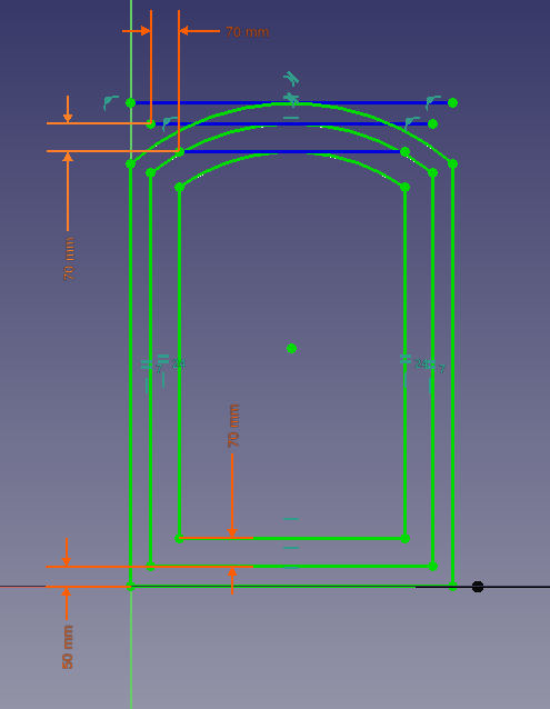
Wiązania dla wewnętrznych linii szkicu tworzących okno.
10. Gdy szkic zostanie w pełni związany, naciśnij Zamknij, aby wyjść ze szkicu (Zamknij szkic).
- 10.1. Ponieważ powierzchnia ściany została wybrana podczas początkowego etapu tworzenia szkicu, szkic jest współpłaszczyznowy z tą powierzchnią. Może jednak znajdować się w niewłaściwym położeniu, z dala od ściany. W takim przypadku należy dostosować DANEPozycję w DANEOdsunięciu dołączenia. Ustaw własciwość DANEPozycja na
[4 m, 1 m, 0 m], aby szkic był wyśrodkowany na ścianie i znajdował się metr nad poziomem podłogi. - 10.2. Nazwane więzy można zobaczyć w DANEWiązaniach. Wartości można zmodyfikować, aby szkic natychmiast zmienił wymiary.
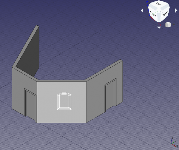
Szkic okna przesunięty do żądanej pozycji na ścianie.
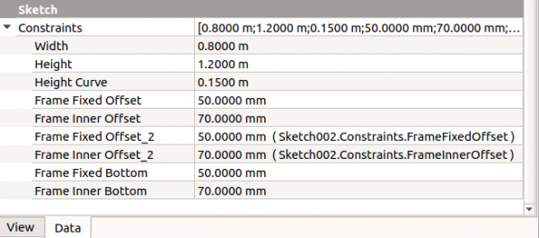
Nazwane wiązania szkicu, które można modyfikować bez wchodzenia do szkicu.
11. Wróć do środowiska pracy Architektura i po wybraniu nowego Sketch002 użyj narzędzia Okno. Okno zostanie utworzone i zrobi dziurę w ścianie. Okno zostało utworzone z niestandardowego szkicu, a nie z ustawienia wstępnego, więc należy je edytować, aby poprawnie wyświetlić jego komponenty, czyli stałą ramę, wewnętrzną ramę i szklany panel.
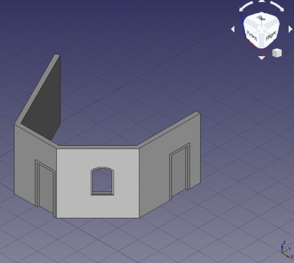
Custom window created from the sketch; it still doesn't have a proper frame, nor glass
Setting up the custom window
12. In the tree view select Sketch002 underlying Window, and press Space, or change the property WIDOKVisibility to true.
13. Double click Window in the tree view to start editing it.
- 13.1. Inside the
Window elementsdialog there are two panes,WiresandComponents. There are three wires,Wire0,Wire1, andWire2, and one component,Default. The wires refer to the closed loops that were drawn in the sketch; the components define the areas in the sketch that will be extruded to create frame or glass panels with real thicknesses; these areas are delimited by the wires. A window created from a preset already has two components,OuterFrameandGlass. The custom window needs to be edited to have a similar structure.
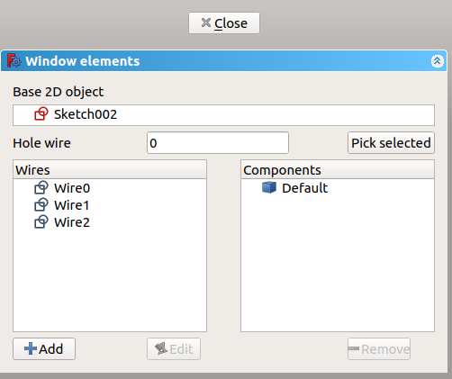
Dialog to edit a window or a door
- 13.2. Click on
Default, and click the Remove button to eliminate it.
- 13.3. Click Add; this shows the properties of a new component like
Name,Type,Wires,Thickness,Offset,Hinge, andOpening mode. Give a name, such asOuterFrame, chooseFrameforType, and click onWire0and thenWire1; they should highlight in the 3D viewport. Add a small value forThickness,15 mm, and check the checkbox to add the default value. This default value is the length assigned to the DANEFrame property; a similar default can be assigned to the DANEOffset property. Click the +Create/update component button to finish editing the component.
- 13.4. Click Add; give another name, such as
InnerFrame, chooseFrameforType, and click onWire1and thenWire2. Add a sensibleThickness,60 mm, andOffset,15 mm. Then click the +Create/update component button.
- 13.5. Click Add; give another name, such as
Glass, chooseGlass panelforType, and click onWire2. Add a sensibleThickness,10 mm, andOffset,40 mm. Then click the +Create/update component button. If any of the three components needs to be modified, select it and press Edit; modifications are only saved after pressing the +Create/update component button.
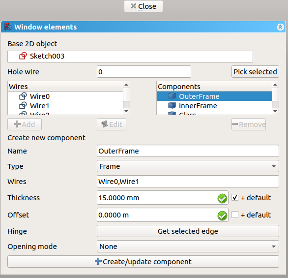
Editing a previously defined component of a window or a door
- 13.6. If everything is set, click Close to finish editing the window. The sketch may become hidden again, but the window will show distinct solid elements for the
OuterFrame, theInnerFrame, and theGlass. Give a value of100 mmto DANEFrame to assign a default thickness, which will be added to the value specified in theOuterFramecomponent.
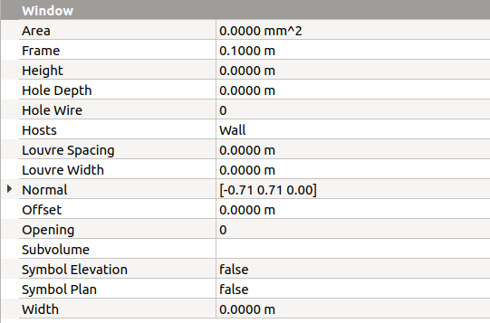
Property view of the window to add default Frame length, Offset length, and other options
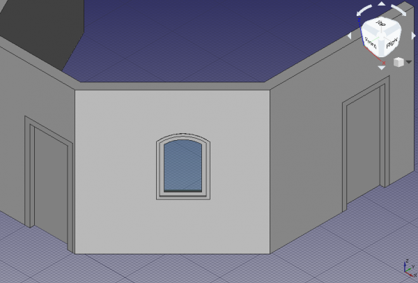
Finished window with appropriate components embedded in the wall
Duplicating the custom window
14. In the tree view, select Window and its underlying Sketch002. Then go to Edit → Duplicate selection, and answer No if asked to duplicate unselected dependencies. A new Window001 and Sketch003 will appear in the same position as the original elements.
15. Select the new Sketch003. Go to the DANEMap Mode property, and click on the ellipsis next to the FlatFace value. In the 3D viewport select the left side of the wall which doesn't have any element; rotate the standard view as necessary. Change the Attachment offset to [-1 m, 0 m, 0 m] to center the window, and click OK. The sketch and the window should appear in a new position.
- Note: the attachment operation can also be performed by changing to the Part Workbench, and then using the menu Part → Attachment.
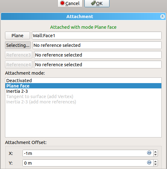
Dialog to edit the attachment plane of the sketch
16. You may adjust the dimensions of the new window by changing the named parameters in Sketch003 under DANEConstraints, for example, set Height to 2 m, and Frame Fixed Bottom to 0 m. Then press Ctrl+R to recompute the model. If the wall doesn't show a bigger hole for the new window, select the wall in the tree view, right click and choose Mark to recompute, then press Ctrl+R again.
17. These operations have changed the position of the new window, but the opening in the wall doesn't look correct. It is slanted, that is, the hole is not perpendicular to the face of the wall, and it may even cut other parts of the wall. The problem is that Window001 has retained the DANENormal information of the original Window.
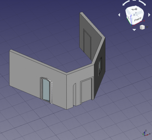
Incorrect opening in the wall due to bad Normal of the window
Normals of doors and windows
18. Each Arch Window object controls the extrusion of its body and the opening that is created in its host wall by means of the DANENormal.
The normal is a vector [x, y, z] that indicates a direction perpedicular to a wall. When a window or door preset is created with the Arch Window tool directly over an Arch Wall, the normal is automatically calculated, and the resulting window or door is correctly aligned; the first two objects, Door and Door001, were created in this way.
In similar way, when a sketch is created by selecting a planar surface, it is oriented on this plane. Then when the Arch Window tool is used, the window will use as normal the perpendicular direction to the sketch. This was the case with the third object, the custom Window.
If the window already exists and needs to be moved, as was the case with the duplicated Window001 object, the sketch needs to be remapped to another plane; doing this moves both the sketch and the window, but the latter doesn't automatically update its normal, so it has incorrect extrusion information. The normal needs to be calculated manually and written to DANENormal.
The three values of the normal vector are calculated as following.
x = -sin(angle)
y = cos(angle)
z = 0
Where angle is the angle of the local Z axis of the sketch with respect to the global Y axis.
When a sketch is created, it always has two axes, a local X (red) and a local Y (green). If the sketch is mapped to the global XY working plane, then these axes are aligned; but if the sketch is mapped on the global XZ or global YZ planes, as is common with windows and doors (the sketches are "standing up"), then the local Z (blue) forms an angle with the global Y axis; this angle varies from -180 to 180 degrees. The angle is considered positive if it opens counterclockwise, and it is negative if it opens clockwise, starting from the global Y axis.
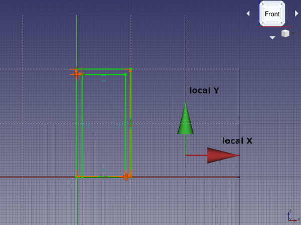
Local coordinates of a sketch that is "standing up", that is, mapped to the global XZ plane
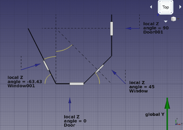
Intended directions of the normals for each door and window
If we look at the geometry created so far, we see the following normals.
Door- The local Z is aligned with the global Y, therefore, the
angleis zero. The normal vector is
x = -sin(0) = 0
y = cos(0) = 1
z = 0
or DANENormal is [0, 1, 0].
Door001- The local Z is rotated 90 degrees from the global Y, therefore, the
angleis 90 (positive, because it opens counterclockwise). The normal vector is
x = -sin(90) = -1
y = cos(90) = 0
z = 0
or DANENormal is [-1, 0, 0].
Window- The local Z is rotated 45 degrees from the global Y, therefore, the
angleis 45 (positive, because it opens counterclockwise). The normal vector is
x = -sin(45) = -0.7071
y = cos(45) = 0.7071
z = 0
or DANENormal is [-0.7071, 0.7071, 0].
Window001- The local Z direction is found by using the Draft Dimension tool and measuring the angle that the wall trace (
Wire) makes with the global Y axis, or any line aligned to it. This angle is26.57; the desired angle is the complement to this, so90 - 26.57 = 63.43.
This means the local Z axis is rotated 63.43 degrees from the global Y, therefore, the angle is -63.46 (negative, because it opens clockwise). The normal vector is
x = -sin(-63.43) = 0.8943
y = cos(-63.43) = 0.4472
z = 0
Therefore DANENormal should be changed to [0.8943, 0.4472, 0].
After doing these changes, recompute the model with Ctrl+R. If the wall doesn't update the hole, select it in the tree view, right click and choose Mark to recompute, then press Ctrl+R again.
19. The orientation of the extrusion of the window is resolved, together with the opening in the wall.
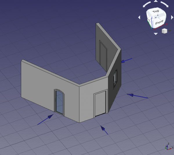
Correct opening in the wall due to proper Normal of the window
Final remarks
20. As demonstrated, the initial placement of the Arch Window is very important. The user should either
- use the Arch Window tool to insert and automatically align a preset to a wall, or
- map a sketch to the desired wall, and build the window after that.
If a window already exists, and it needs to be moved, the supporting sketch should be remapped to a new plane, and the DANENormal of the window needs to be recalculated.
The new normal direction can be obtained by measuring the angle of the new wall with respect to the global Y axis, considering whether this angle is positive (counterclockwise) or negative (clockwise), and using a simple formula.
x = -sin(angle)
y = cos(angle)
z = 0
To confirm that the operations are correct, the absolute magnitude of the normal vector should be one. That is,
abs(N) = 1 = sqrt(x^2 + y^2 + z^2)
abs(N) = 1 = sqrt(sin^2(angle) + cos^2(angle) + z^2)
- Elementy: Mury, Konstrukcja, ściana kurtynowa, Okna, Drzwi, Dach, Kubatura, Schody, Wyposażenie, Ramy, Ogrodzenie, Kratownica, Profil, Rura, Kształtka
- Zbrojenie: Pręty zbrojeniowe proste, Pręty zbrojeniowe typu U, Pręty zbrojeniowe typu L, Strzemiona, Strzemiona, Pręty zbrojeniowe spiralne, Zbrojenie słupów, Zbrojenie belek, Zbrojenie płyt stropowych, Zbrojenie stóp fundamentowych, Pręt zbrojeniowy
- Panels: Panel, Panelizacja do cięcia, Arkusz panela, Zagnieżdżanie
- Materiał: Wybór materiału, Materiał złożony
- Organizacja: Część budowli, Projekt, Teren, Budowla, Piętro, Odniesienie, Płaszczyzna przekroju, Obmiar
- Osie: Osie, Układ osi, Siatka
- Modifikacja: Płaszczyzna cięcia, Komponent dodaj, Komponent usuń, Przegląd
- Narzędzia: Komponent, Klonuj komponent, Podziel siatkę, Siatka na kształt, Zaznacz siatki nie bryłowe, Usuń kształt., Zamknij otwory, Połącz ściany, Sprawdź, Przełącz flagę Brep IFC, Trzy widoki, Arkusz kalkulacyjny IFC, Przełącz widoczność odjęcia
- Dodatkowe: Preferencje, Ustawienia Importu i Eksportu (IFC, DAE, OBJ, JSON, 3DS); SHP), Architektura: API
- Kreślenie: Linia, Polilinia, Zaokrąglenie, Łuk, Łuk przez 3 punkty, Okrąg, Elipsa, Wielokąt foremny, Krzywa złożona, Krzywa Bezier'a, Punkt, Łącznik ścian, Kształt z tekstu, Kreskowanie, Prostokąt
- Adnotacje: Adnotacja wieloliniowa, Wymiarowanie, Etykieta, Edytor stylów adnotacji, Widżet skali anotacji
- Modyfikacja: Przesuń, Obróć, Skala, Odbicie lustrzane, Odsunięcie, Przytnij, Rozciągnij, Klonuj, Szyk, Szyk biegunowy, Szyk kołowy, Szyk po ścieżce, Szyk powiązań po ścieżce, Szyk z punktów, Szyk powiązań w punktach, Edycja, Podświetl element podrzędny, Połącz, Rozdziel, Ulepsz kształt, Rozbij obiekt na elementy, Polilinia na krzywą złożoną, Rysunek Roboczy do szkicu, Nachylenie, Obróć wymiar, Widok 2D kształtu
- Tacka narzędziowa: Wybór płaszczyzny, Ustaw styl, Przełącz tryb konstrukcyjny, Grupowanie automatyczne
- Przyciąganie: Przełącz przyciąganie, Przyciągnij do punktu końcowego, Przyciągnij do punktu środkowego, Przyciągnij do środka, Przyciągnij do kąta, Przyciąganie do punktu przecięcia, Przyciągnij prostopadle, Rozszerz, Przyciągnij równolegle, Przyciągnij specjalnie, Przyciąganie do najbliższego, Przyciągnij ortogonalnie, Przyciągnij do siatki, Przyciągnij do płaszczyzny roboczej, Przyciągnij do wymiaru, Pokaż / ukryj siatkę
- Różności: Zastosuj bieżący styl, Warstwa, Zarządzaj warstwami, Dodaj grupę o nazwie, Dodaj do grupy, Wybierz grupę, Dodaj do grupy konstrukcyjnej, Przełącz tryb wyświetlania, Pośrednia płaszczyzna robocza, Ulecz, Przełącz tryb kontynuacji, Pokaż przybornik przyciągania
- Dodatkowe:: Wiązania, Wypełnienie wzorem, Preferencje, Ustawienia Importu i Eksportu, DXF/DWG, SVG, OCA, DAT
- Menu podręczne:
- Kontener warstwy: Połącz duplikaty warstw, Dodaj warstwę
- Warstwa: Aktywuj warstwę, Zaznacz zawartość warstwy
- Pośrednia płaszczyzna robocza: Zapisz ujęcie widoku, Zapisz stan obiektów
- Przybory: Nowy szkic, Edycja szkicu, Mapuj szkic na powierzchnię, Zmień orientację szkicu, Sprawdź poprawność szkicu, Połącz szkice, Odbicie lustrzane szkicu, Zamknij szkic, Widok szkicu, Widok przekroju, Włącz / wyłącz siatkę, Włącz / wyłącz przyciąganie, Kolejność renderowania, Przerwij operację
- Geometrie szkicownika: Punkt, Linia, Komponent utwórz łuk, Łuk, Utwórz łuk przez 3 punkty, Komponent utwórz okrąg, Okrąg, Utwórz okrąg przez 3 punkty, Komponent utwórz stożek, Utwórz elipsę względem środka, Utwórz elipsę przez 3 punkty, Utwórz łuk elipsy, Utwórz łuk hyperboli, Utwórz łuk paraboli, Komponent utwórz krzywą złożoną, Utwórz krzywą złożoną, Utwórz okresową utwórz krzywą złożoną, Polylinia (linia wielopunktowa), Prostokąt, Komponent utwórz wielokąt foremny, Trójkąt, Kwadrat, Pięciokąt, Sześciokąt, Siedmiokąt, Ośmiokąt, Utwórz wielokąt foremny, Rowek, Zaokrąglenie, Zaokrąglenie z zachowaniem wiązań, Przytnij, Rozszerz, Geometria zewnętrzna, Kalka techniczna, Tryb konstrukcyjny
- Wiązania szkicownika
- Wiązania geometryczne Wiązanie zbieżności punktów, Wiązanie punktu na obiekcie, Wiązanie pionowe, Wiązanie poziome, Wiązanie równoległości, Wiązanie prostopadłości, Wiązanie styczności, Wiązanie równości, Wiązanie symetrii, Wiązanie zablokowania
- Wiązania wymiarów Wiązanie blokady odległości, Zwiąż odległość poziomą, Zwiąż odległość pionową, Wiązanie odległości, Wiązanie promienia, Wiązanie średnicy, Zwiąż automatycznie promień / średnicę, Wiązanie kąta, Wiązanie prawo Snella
- Narzędzia wiązań: Przełącz kontrolę wiązania, Przełącz aktywność wiązania
- Narzędzia szkicownika Wybierz elementy bez wiązań, Wybierz powiązane więzy, Wybierz powiązaną geometrię, Wybierz zbędne wiązania, Wybierz wiązania konfliktowe, Pokaż / ukryj geometrię wewnętrzną, Wybierz odniesienie położenia, Wybierz oś poziomą, Wybierz oś pionową, Odbicie lustrzane, Klonuj, Kopiuj, Przesuń, Szyk prostokątny, Usuń wyrównanie osi, Usuń wszystkie geometrie, Usuń wszystkie wiązania
- Narzędzia B-spline dla szkicownika. Pokaż / ukryj stopień krzywej złożonej, Pokaż/ukryj ramkę kontrolną krzywej złożonej, Pokaż / ukryj grzebień krzywizny krzywej złożonej, Pokaż / ukryj wyświetlanie węzłów krzywej złożonej, Pokaż / ukryj wagę punktu kontrolnego krzywej złożonej, Konwertuj geometrię na krzywą złożoną, Zwiększ stopień krzywej złożonej, Zmniejsz stopień krzywej złożonej, Zwiększ krotność węzłów krzywej złożonej, Zmniejsz krotność węzła krzywej złożonej, Wstaw węzeł, Połącz krzywe
- Przestrzeń wirtualna szkicownika Przełącz przestrzeń wirtualną
- Dodatkowe: Okienko dialogowe Szkicownika, Preferencje, Skrypty Szkicownika
- Jak zacząć
- Instalacja: Pobieranie programu, Windows, Linux, Mac, Dodatkowych komponentów, Docker, AppImage, Ubuntu Snap
- Podstawy: Informacje na temat FreeCAD, Interfejs użytkownika, Profil nawigacji myszką, Metody wyboru, Nazwa obiektu, Edytor ustawień, Środowiska pracy, Struktura dokumentu, Właściwości, Pomóż w rozwoju FreeCAD, Dotacje
- Pomoc: Poradniki, Wideo poradniki
- Środowiska pracy: Strona Startowa, Architektura, Assembly, CAM, Rysunek Roboczy, MES, Inspekcja, Siatka, OpenSCAD, Część, Projekt Części, Punkty, Inżynieria Wsteczna, Robot, Szkicownik, Arkusz Kalkulacyjny, Powierzchnia 3D, Rysunek Techniczny, Test Framework