Sketcher Micro Tutorial - Constraint Practices/pl: Difference between revisions
No edit summary |
No edit summary |
||
| Line 123: | Line 123: | ||
* [[Basic_Sketcher_Tutorial/pl|Poradnik: Podstawy dla Środowiska pracy Sketcher]] |
* [[Basic_Sketcher_Tutorial/pl|Poradnik: Podstawy dla Środowiska pracy Sketcher]] |
||
* [[Sketcher_reference|Sketcher |
* [[Sketcher_reference|Sketcher - powiązania]] |
||
* [[Sketcher_Tutorial/pl|Poradnik dla Środowiska pracy Sketcher]] |
* [[Sketcher_Tutorial/pl|Poradnik dla Środowiska pracy Sketcher]] |
||
Revision as of 16:30, 4 March 2020
| Temat |
|---|
| Modelowanie |
| Poziom trudności |
| początkujący |
| Czas wykonania |
| 30 minut |
| Autorzy |
| Mark Stephen (Quick61) and vocx |
| Wersja FreeCAD |
| 0.19 |
| Pliki z przykładami |
| Sketcher: wiązania praktycznie |
| Zobacz również |
| - |
Wprowadzenie
This tutorial was originally written by Quick61, and it was rewritten and reillustrated by vocx.
Witamy
Ten poradnik ma na celu pomóc nowemu użytkownikowi FreeCAD zapoznać się z technikami i najlepszymi praktykami dotyczącymi tworzenia wiązań szkicu oraz przepływem pracy Środowiska Sketcher.
Szybkie objaśnienie
Istnieje ogólna zasada z wykorzystaniem wiązań szkicownika FreeCAD, im mniej jest wiązań wymiarowych, tym lepiej. Jeśli jest to możliwe, zawsze lepiej jest użyć wiązania geometrycznego zamiast wymiarowego. Ma to związek z wewnętrznym funkcjonowaniem solvera Środowiska Sketcher.
It is preferable to use a geometric constraint in place of a dimensional one if possible. This has to do with the internal workings of the Sketcher's constraint solver.
Setup
1. Open FreeCAD, create a new empty document with File → New.
- 1.1. Switch to the Sketcher Workbench from the workbench selector, or the menu View → Workbench → Sketcher.
Some actions to remember:
- Press the right mouse button, or press Esc in the keyboard once, to deselect the active tool in edit mode.
- To exit the sketch edit mode, press the Close button in the task panel, or press Esc twice in the keyboard.
- To enter again edit mode, double click on the sketch in the tree view, or select it, and then click on
Edit sketch.
Create a sketch
2. Click on New sketch.
- 2.1. Choose the sketch orientation, that is, one of the base XY, XZ, or YZ planes. We will use the default plane and options.
- 2.2. Click OK to start constructing the sketch.
Note: in the task panel expand the Edit controls section, and make sure the Auto constraints option is disabled. Also turn off the grid snap, and hide the grid.
Podejście pierwsze
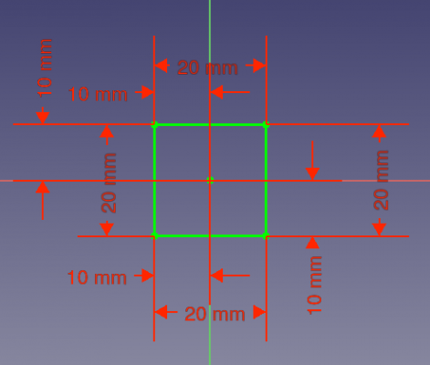
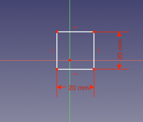
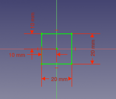
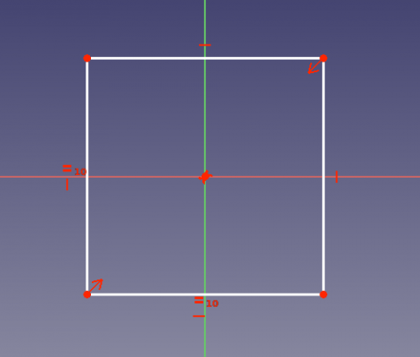
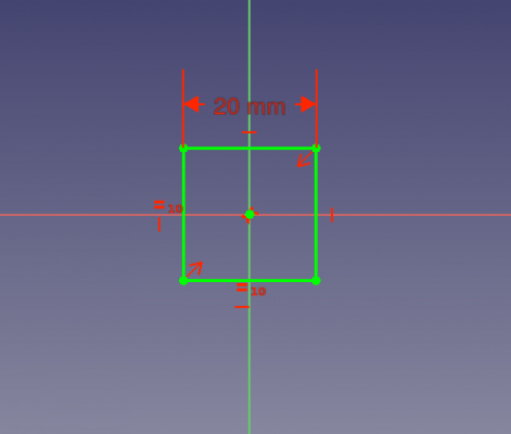
Jako przykład, weźmy szkic kwadratu. Na pierwszym obrazie szkic jest w pełni związany, ale używa tylko wiązań wymiarów, (odległość). To jest OK, ale zbyt skomplikowane, zagmatwane i bardziej matematycznie zaawansowane dla solvera. Chociaż nie stanowi to problemu w tak prostym przykładzie, to może stać się problemem w bardziej skomplikowanym szkicu.
3. We will draw a fully constrained square, centered at the origin.
- 3.1. Click on
Create polyline, then trace four lines in the general shape of a rectangle around the origin.
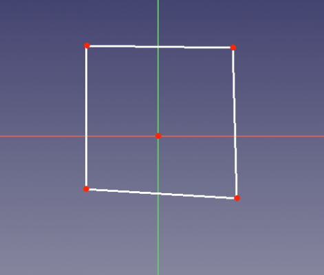
Unconstrained rectangular sketch.
- 3.2. Select one horizontal line, and press
Horizontal distance, then enter
20 mm. - 3.3. Select the other horizontal line, and repeat the constraint with the same distance.
- 3.4. Select one vertical line, and press
Vertical distance, then enter
20 mm. - 3.5. Select the other vertical line, and repeat the constraint with the same distance.
- 3.6. Select one bottom corner point (a), and the origin of the sketch, and press
Horizontal distance, then enter
10 mm. - 3.7. Select the top corner point (b) above the previous corner point (a), and the origin of the sketch, and repeat the horizontal constraint with the same distance.
- 3.8. Select the other bottom corner point (c), and the origin of the sketch, and press
Vertical distance, then enter
10 mm. - 3.9. Select the top corner point (b) again, and the origin of the sketch, and repeat the vertical constraint with the same distance.
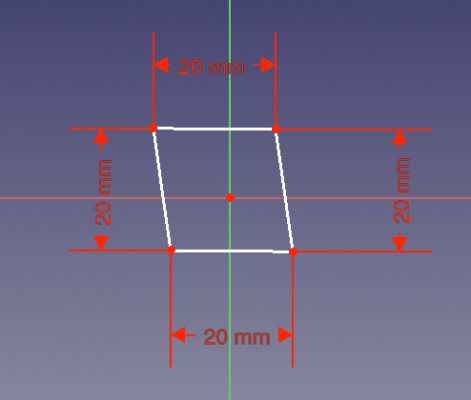
Left: datum constraints for the sides. Right: additional datum constraints for the interior distances.
Looking at the Constraints section in the task panel, we see that the constraints are too many; they also clutter the view of the sketch. These constraints are also computationally intensive for the solver; while this is not an issue with a simple shape, it can become one with more complex shapes.
Lepsza droga
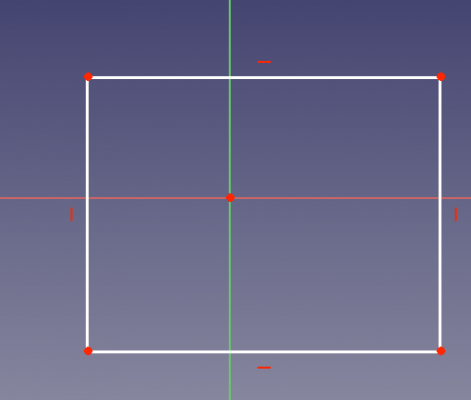
Następny zrzut ekranu przedstawia ten sam kwadrat, ograniczony przy użyciu pewnych wiązań geometrycznych. Zastosowano poziome i pionowe wiązania geometryczne, wraz z wiązaniami wymiarów (odległości). Używając tylko poziomych i pionowych wiązań geometrycznych, można zobaczyć, że liczba wymaganych ograniczeń wymiarowych została zmniejszona. Jest to lepszy szkic z wiązaniami niż pierwszy, ale nadal nie jest to optymalny schemat wiązań dla tego kwadratu.
4. We will draw the same square fully constrained, and centered at the origin. When you create the new sketch, make sure the Auto constraints option is disabled.
- 4.1. Click on
Create polyline, then trace four lines in the general shape of a rectangle around the origin.
- 4.2. Select one horizontal line, and press
Horizontal.
- 4.3. Select the other horizontal line, and repeat the constraint.
- 4.4. Select one vertical line, and press
Vertical.
- 4.5. Select the other vertical line, and repeat the constraint.
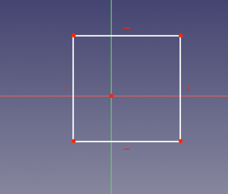
Geometrical horizontal and vertical constraints.
- 4.6. Select one horizontal line, and press
Horizontal distance, then enter
20 mm. We see that the other horizontal line changes size at the same time. - 4.7. Select one vertical line, and press
Vertical distance, then enter
20 mm. We see that the other vertical line changes size at the same time. - 4.8. Select one bottom corner point (a), and the origin of the sketch, and press
Horizontal distance, then enter
10 mm. - 4.9. Select the top corner point (b) above the previous corner point (a), and the origin of the sketch, and press
Vertical distance, then enter
10 mm.
Left: datum constraints for only two sides. Right: additional datum constraints for only two interior distances.
This is a better constrained sketch than the first one. The horizontal and vertical geometric constraints allow us to use fewer datum constraints, so our sketch looks less cluttered.
Schemat optymalny
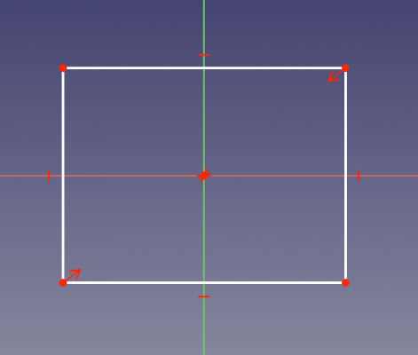
Teraz, na tym ostatnim zrzucie ekranu, jest tylko 1 wymiar, (odległość), ograniczenie, a pozostałe są to wiązania geometryczne. Jest to najlepszy sposób na związanie tego szkicu. Podczas gdy w przypadku takiego prostego szkicu, taki czy inny sposób nie jest niczym wielkim, w przypadku większych i bardziej złożonych szkiców, trzymanie się zasady minimum wymiarów okaże się korzystne dla ciebie i twoich wysiłków związanych z konstruowaniem geometrii za pomocą szkiców. Stosowane w tym szkicu wiązania geometryczne to: pozioma, pionowa, równość i symetria.
5. We will draw the same square fully constrained, and centered at the origin. When you create the new sketch, make sure the Auto constraints option is disabled.
- 5.1. Click on
Create polyline, then trace four lines in the general shape of a rectangle around the origin.
- 5.2. Select one horizontal line, and press
Horizontal.
- 5.3. Select the other horizontal line, and repeat the constraint.
- 5.4. Select one vertical line, and press
Vertical.
- 5.5. Select the other vertical line, and repeat the constraint.
Geometrical horizontal and vertical constraints.
- 5.6. Select one bottom corner point (a), then the top corner point that is diagonally opposite, and then the origin of the sketch; then press
Symmetric. The two selected points will be equidistant from the origin.
- 5.7. Select two adjacent sides of the rectangle (connected at one corner), and press
Equal length. Notice that due to the symmetry of the corner points, all sides are now of the same size.
Left: symmetric constraint for only two corner points. Right: additional equal length distances for only two adjacent sides.
- 5.8. Select one horizontal line, and press
Horizontal distance, then enter
20 mm. Due to the symmetric and length equality constraints previously added, we see that all sides become equal at the same time.
All geometric constraints applied, and a single datum constraint for a side.
This is the best way to constrain this sketch, as we only used one datum (dimensional) constraint.
Dodatkowe zasoby
- Poradnik: Podstawy dla Środowiska pracy Sketcher
- Sketcher - powiązania
- Poradnik dla Środowiska pracy Sketcher
- Przybory: Nowy szkic, Edycja szkicu, Mapuj szkic na powierzchnię, Zmień orientację szkicu, Sprawdź poprawność szkicu, Połącz szkice, Odbicie lustrzane szkicu, Zamknij szkic, Widok szkicu, Widok przekroju, Włącz / wyłącz siatkę, Włącz / wyłącz przyciąganie, Kolejność renderowania, Przerwij operację
- Geometrie szkicownika: Punkt, Linia, Komponent utwórz łuk, Łuk, Utwórz łuk przez 3 punkty, Komponent utwórz okrąg, Okrąg, Utwórz okrąg przez 3 punkty, Komponent utwórz stożek, Utwórz elipsę względem środka, Utwórz elipsę przez 3 punkty, Utwórz łuk elipsy, Utwórz łuk hyperboli, Utwórz łuk paraboli, Komponent utwórz krzywą złożoną, Utwórz krzywą złożoną, Utwórz okresową utwórz krzywą złożoną, Polylinia (linia wielopunktowa), Prostokąt, Komponent utwórz wielokąt foremny, Trójkąt, Kwadrat, Pięciokąt, Sześciokąt, Siedmiokąt, Ośmiokąt, Utwórz wielokąt foremny, Rowek, Zaokrąglenie, Zaokrąglenie z zachowaniem wiązań, Przytnij, Rozszerz, Geometria zewnętrzna, Kalka techniczna, Tryb konstrukcyjny
- Wiązania szkicownika
- Wiązania geometryczne Wiązanie zbieżności punktów, Wiązanie punktu na obiekcie, Wiązanie pionowe, Wiązanie poziome, Wiązanie równoległości, Wiązanie prostopadłości, Wiązanie styczności, Wiązanie równości, Wiązanie symetrii, Wiązanie zablokowania
- Wiązania wymiarów Wiązanie blokady odległości, Zwiąż odległość poziomą, Zwiąż odległość pionową, Wiązanie odległości, Wiązanie promienia, Wiązanie średnicy, Zwiąż automatycznie promień / średnicę, Wiązanie kąta, Wiązanie prawo Snella
- Narzędzia wiązań: Przełącz kontrolę wiązania, Przełącz aktywność wiązania
- Narzędzia szkicownika Wybierz elementy bez wiązań, Wybierz powiązane więzy, Wybierz powiązaną geometrię, Wybierz zbędne wiązania, Wybierz wiązania konfliktowe, Pokaż / ukryj geometrię wewnętrzną, Wybierz odniesienie położenia, Wybierz oś poziomą, Wybierz oś pionową, Odbicie lustrzane, Klonuj, Kopiuj, Przesuń, Szyk prostokątny, Usuń wyrównanie osi, Usuń wszystkie geometrie, Usuń wszystkie wiązania
- Narzędzia B-spline dla szkicownika. Pokaż / ukryj stopień krzywej złożonej, Pokaż/ukryj ramkę kontrolną krzywej złożonej, Pokaż / ukryj grzebień krzywizny krzywej złożonej, Pokaż / ukryj wyświetlanie węzłów krzywej złożonej, Pokaż / ukryj wagę punktu kontrolnego krzywej złożonej, Konwertuj geometrię na krzywą złożoną, Zwiększ stopień krzywej złożonej, Zmniejsz stopień krzywej złożonej, Zwiększ krotność węzłów krzywej złożonej, Zmniejsz krotność węzła krzywej złożonej, Wstaw węzeł, Połącz krzywe
- Przestrzeń wirtualna szkicownika Przełącz przestrzeń wirtualną
- Dodatkowe: Okienko dialogowe Szkicownika, Preferencje, Skrypty Szkicownika
- Jak zacząć
- Instalacja: Pobieranie programu, Windows, Linux, Mac, Dodatkowych komponentów, Docker, AppImage, Ubuntu Snap
- Podstawy: Informacje na temat FreeCAD, Interfejs użytkownika, Profil nawigacji myszką, Metody wyboru, Nazwa obiektu, Edytor ustawień, Środowiska pracy, Struktura dokumentu, Właściwości, Pomóż w rozwoju FreeCAD, Dotacje
- Pomoc: Poradniki, Wideo poradniki
- Środowiska pracy: Strona Startowa, Architektura, Assembly, CAM, Rysunek Roboczy, MES, Inspekcja, Siatka, OpenSCAD, Część, Projekt Części, Punkty, Inżynieria Wsteczna, Robot, Szkicownik, Arkusz Kalkulacyjny, Powierzchnia 3D, Rysunek Techniczny, Test Framework
