Poradnik: Kula Whiffle
| Temat |
|---|
| Projekt produktu |
| Poziom trudności |
| początkujący |
| Czas wykonania |
| 30 minut |
| Autorzy |
| r-frank oraz vocx |
| Wersja FreeCAD |
| 0.17 inowszy |
| Pliki z przykładami |
| WhiffleBall_Tutorial_FCWiki.FCStd |
| Zobacz również |
| - |
Wprowadzenie
Ten poradnik został pierwotnie napisany przez Rolanda Franka (†2017, r-frank), a następnie przepisany i zilustrowany przez vocx.
W tym poradniku dowiesz się, jak korzystać ze środowiska Część.
Środowisko pracy Część było pierwszym opracowanym środowiskiem pracy. Zapewnia ono podstawowe elementy geometryczne, które mogą być używane jako bloki konstrukcyjne dla innych środowisk pracy. Środowisko pracy Część jest przeznaczone do stosowania w tradycyjnym przepływie pracy konstrukcyjna geometria bryłowa (CSG). Aby uzyskać bardziej nowoczesny przepływ pracy z wykorzystaniem szkiców, wyciągnięć i cech, należy użyć środowiska pracy Projekt Części.
Będziesz ćwiczyć:
- wstawianie elementów pierwotnych,
- zmienianie parametrów tych obiektów pierwotnych,
- modyfikowanie ich umiejscowienia,
- wykonywanie operacji logicznych.
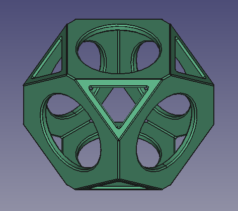
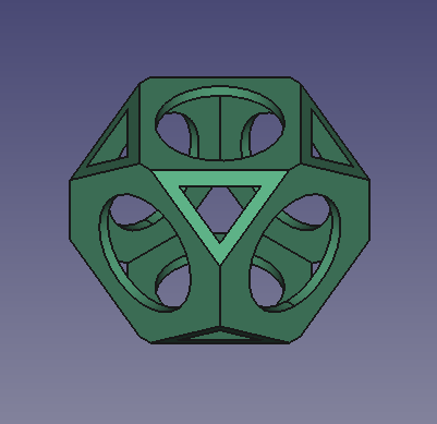
Ostateczny model kuli wiffle.
Konfiguracja
1. Uruchom FreeCAD, utwórz nowy pusty dokument za pomocą Plik → Nowy i przełącz się na środowisko Part Workbench.
- 1.1. Naciśnij przycisk
Widok izometryczny lub naciśnij 0 na klawiaturze numerycznej, aby zmienić widok na izometryczny w celu lepszej wizualizacji brył w widoku 3D.
- 1.2. Naciśnij przycisk
Przybliż i dopasuj wszystko za każdym razem, gdy dodajesz obiekty, aby przesuwać i powiększać widok 3D tak, aby wszystkie elementy były widoczne w widoku.
- 1.3. Przytrzymaj Ctrl podczas klikania, aby zaznaczyć wiele elementów. Jeśli wybrałeś coś źle lub chcesz usunąć zaznaczenie, kliknij na puste miejsce w widok 3D.
Wstaw sześcian pierwotny
2. Wstaw sześcian pierwotny, klikając w Sześcian.
- 2.1. Wybierz
Sześcianw oknie widoku drzewa. - 2.2. Zmień wymiary w zakładce Dane edytora właściwości.
- 2.3. Zmień Długość na
90 mm. - 2.4. Zmień Szerokość na
90 mm. - 2.5. Zmień Wysokość na
90 mm.
3. W zakładce Dane w edytorze właściwości kliknij na wartość Umiejscowienie, aby po prawej stronie pojawił się przycisk wielokropka ….
- 3.1. Naciśnij wielokropek, aby uruchomić okno dialogowe Umiejscowienie.
- 3.2. Zmień wartości Przesunięcie.
- 3.3. Zmień X na
-45 mm. - 3.4. Zmień Y na
-45 mm. - 3.5. Zmień Z na
-45 mm. - 3.6. Naciśnij przycisk OK, aby zamknąć okno dialogowe.
4. Powtórz proces, wstawiając drugą, mniejszą kostkę, klikając Sześcian.
- 4.1. Drugi sześcian zostanie utworzony z tą samą nazwą, ale z dodatkowym numerem, aby rozróżnić obiekt.
- 4.2. W oknie widoku drzewa wybierz
Cube001, a następnie zmień jego wymiary i położenie, tak jak w przypadku poprzedniego obiektu. - 4.3. Zmień Długość na
80 mm. - 4.4. Zmień Szerokość na
80 mm. - 4.5. Zmień Wysokość na
80 mm. - 4.6. Otwórz okno dialogowe Umiejscowienie.
- 4.7. Zmień X na
-40 mm. - 4.8. Zmień Y na
-40 mm. - 4.9. Zmień Z na
-40 mm. - 4.10. Naciśnij przycisk OK, aby zamknąć okno dialogowe.
Zmiana właściwości wyglądu
5. Poprzednie operacje utworzyły mniejszy sześcian wewnątrz większego sześcianu. Aby to zwizualizować, możemy zmodyfikować właściwość Widok w edytorze właściwości.
- 5.1. Wybierz
Cube001, mniejszą kostkę, w oknie widoku drzewa i zmień jej kolor. W zakładce Widok kliknij wartość Kolor kształtu, aby otworzyć okno dialogowe Wybierz kolor, a następnie wybierz kolor zielony, zmień także wartość Szerokość linii na2.0. - 5.2. Wybierz obiekt
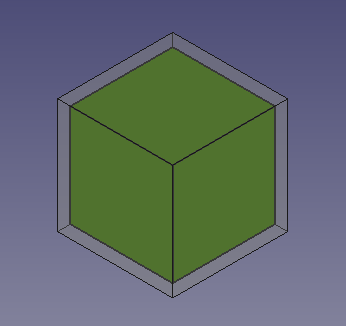
Sześcian, większy sześcian, w oknie widok drzewa. W zakładce Widok zmień wartość Przezroczystość na70.5. Poprzednie operacje utworzyły mniejszy sześcian wewnątrz większego sześcianu. Aby to zwizualizować, możemy zmodyfikować właściwości Widoku w edytorze właściwości.
Bryła sześcianu wewnątrz innej bryły sześcianu.
Wstaw walec pierwotny
6. Wstaw cylinder pierwotny klikając na Cylinder.
- 6.1. Wybierz Template:Inkod w oknie widoku drzewa.
- 6.2. Zmień wymiary w zakładce Dane edytora właściwości.
- 6.3. Zmień Promień na
27.5 mm. - 6.4. Zmień Wysokość na
120 mm. - 6.5. Otwórz okno dialogowe Umiejscowienie.
- 6.6. Zmień Z na
-60 mm. - 6.7. Naciśnij przycisk OK, aby zamknąć okno dialogowe.
7. Powtórz proces, wstawiając drugi cylinder, klikając Cylinder.
- 7.1. Drugi cylinder zostanie utworzony z tą samą nazwą, ale z dodatkowym numerem, aby rozróżnić obiekt.
- 7.2. Wybierz obiekt
Cylinder001w oknie widoku drzewa, a następnie zmień jego wymiary i położenie, tak jak w przypadku poprzedniego obiektu. - 7.3. Zmień Promień na
27.5 mm. - 7.4. Zmień Wysokość na
120 mm. - 7.5. Otwórz okno dialogowe Umiejscowienie.
- 7.6. Zmień Y na
60 mm. - 7.7. Zmień właściwość Obrót na
ROś obrotu z zadanym kątem; Oś naX(ustawiając wartościX,YiZpól wprowadzania osi odpowiednio na1,0i0) oraz Kąt na90°. - 7.8. Naciśnij przycisk OK, aby zamknąć okno dialogowe.
8. Insert another cylinder. This time create a duplicate so that the radius and height don't have to be changed, only its placement.
- 8.1. Select
Cylinder001in the tree view, and go to the menu Edit → Duplicate selection. This will createCylinder002. - 8.2. Open the Placement dialog.
- 8.3. Change X to
-60 mm, and change Y back to0 mm. - 8.4. Change the Rotation to
Rotation axis with angle; Axis toY, and Angle to90 deg. - 8.5. Press the OK button to close the dialog.
Change visual properties
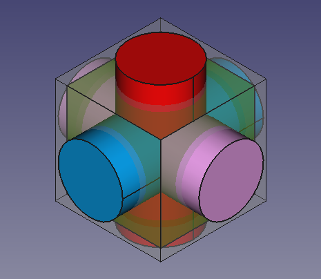
9. The previous operations create three cylinders that intersect with each other, and also intersect the cubes. To visualize this better we can modify the View properties in the property editor.
- 9.1. Select
Cube001, the smaller cube, in the tree view, and change the transparency. In the View tab, change the value of Transparency to70. - 9.2. Select
Cylinder, in the View tab, click on the Shape Color value to open the Select color dialog, then choose a red color. - 9.3. Select
Cylinder001, in the View tab, click on the Shape Color value to open the Select color dialog, then choose a blue color. - 9.4. Select
Cylinder002, in the View tab, click on the Shape Color value to open the Select color dialog, then choose a pink color. - 9.5. Select the three cylinders, in the View tab also change the value of Line Width to
2.0.
Solid cylinders that intersect themselves and the solid cubes.
Fuse and cut
10. In the tree view, select Cube001 (the inner, smaller cube), and the tree cylinders, then press Fuse. This will create a
Fusion object.
11. Then perform a boolean cut of the Cube (larger cube) and the new Fusion object.
- 11.1. In the tree view select
Cubefirst, and thenFusion. - 11.2. Then press
Cut. This will create a
Cutobject. - Note: the order in which you select the objects is important for the cut operation. The base object is selected first, and the subtracting object comes at the end.
- 11.3. If the colors look strange, select the new
Cutobject, go to the View tab, click on the Shape Color value to open the Select color dialog, then choose a gray color; also change the value of Line Width to2.0.
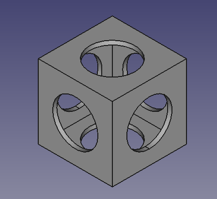
Hollow shape produced from cutting a cube and three cylinders from a bigger cube.
Insert primitive cubes to cut the corners of the partial solid
Now we'll create more cubes that will be used as cutting tools to trim the corners of the previously obtained Cut object.
12. Click on Box.
- 12.1. Select
Cube002in the tree view, and change the dimensions and placement. - 12.2. Change Length to
140 mm. - 12.3. Change Width to
112 mm. - 12.4. Change Height to
112 mm. - 12.5. Open the Placement dialog.
- 12.6. Change X to
-70 mm. - 12.7. Change Y to
-56 mm. - 12.8. Change Z to
-56 mm. - 12.9. Press OK.
13. Click on Box.
- 13.1. Select
Cube003in the tree view, and change the dimensions and placement. - 13.2. Change Length to
180 mm. - 13.3. Change Width to
180 mm. - 13.4. Change Height to
180 mm. - 13.5. Open the Placement dialog.
- 13.6. Change X to
-90 mm. - 13.7. Change Y to
-90 mm. - 13.8. Change Z to
-90 mm. - 13.9. Press OK.
We'll duplicate the previous two objects again to use once more as cutting objects.
14. Select only Cube002 in the tree view, and go to Edit → Duplicate selection. This will create Cube004.
15. Select only Cube003 in the tree view, and go to Edit → Duplicate selection. This will create Cube005.
16. To visualize this better we can modify the View properties in the property editor.
- 16.1. Select the
Cutobject, in the View tab, click on the Shape Color value to open the Select color dialog, then choose a blue color. - 16.2. Select all new cubes,
Cube002,Cube003,Cube004, andCube005, in the View tab, change the value of Transparency to80.
Additional external cubes that will be used as cutting objects for the internal solid.
Cutting the corners 1
17. In the tree view select Cube002 and Cube003.
- 17.1. Open the Placement dialog.
- 17.2. Tick the option Apply incremental changes; notice that all Translation values are reset to zeroes.
- 17.3. Change the Rotation to
Rotation axis with angle; Axis toX, and Angle to45 deg, then click on Apply. This will apply a rotation around the X-axis, and will reset the Angle field to zero. - 17.4. Change the Rotation again, now Axis to
Z, and Angle to45 deg, then click on Apply. This will apply a rotation around the local Z-axis, and will reset the Angle field to zero. - 17.5. Click on OK to close the dialog.
18. In the tree view de-select the objects; then select Cube003 first, the bigger cube, and then Cube002, the smaller cube.
- 18.1. Then press
Cut. This will create
Cut001. This is a hollowed body which intersects the initialCutonly at certain corners.
19. To visualize this better we can modify the View properties in the property editor.
- 19.1. Select
Cube004andCube005, in the View tab, then change the value of Visibility tofalse, or press Space in the keyboard. - 19.2. Select
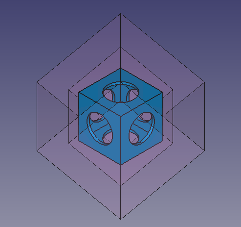
Cut001, click on the Shape Color value to open the Select color dialog, then choose a red color; also change the value of Transparency to90.
A rotated, hollowed solid, which will be used as a cutting object for some corners of the internal solid.
Cutting the corners 2
20. In the tree view select Cut001, in the View tab, change the value of Visibility to false, or press Space in the keyboard.
21. In the tree view select Cube004 and Cube005, in the View tab, change the value of Visibility to true, or press Space in the keyboard.
- 21.1. Open the Placement dialog.
- 21.2. Tick the option Apply incremental changes; notice that all Translation values are reset to zeroes.
- 21.3. Change the Rotation to
Rotation axis with angle; Axis toX, and Angle to45 deg, then click on Apply. This will apply a rotation around the X-axis, and will reset theAnglefield to zero. - 21.4. Change the Rotation again, now Axis to
Z, and Angle to-45 deg, then click on Apply. This will apply a rotation around the local Z-axis, and will reset the Angle field to zero. - 21.5. Click on OK to close the dialog.
22. In the tree view de-select the objects; then select Cube005 first, the bigger cube, and then Cube004, the smaller cube.
- 22.1. Then press
Cut. This will create
Cut002. This is a hollowed body which intersects the initialCutonly at certain corners.
23. To visualize this better we can modify the View properties in the property editor.
- 23.1. Select
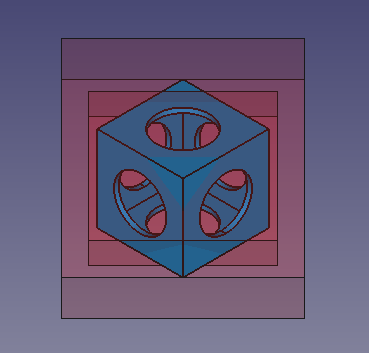
Cut002, click on the Shape Color value to open the Select color dialog, then choose a pink color; also change the value of Transparency to90.
A rotated, hollowed solid, which will be used as a cutting object for some corners of the internal solid.
Finishing the model
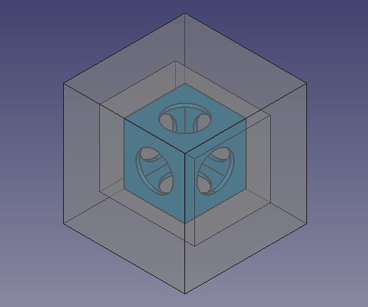
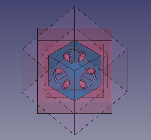
24. Make sure all objects are visible. In the tree view select all objects, in the View tab, change the value of Visibility to true, or press Space in the keyboard.
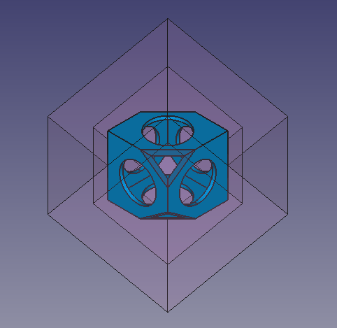
The internal hollowed solid, together with the external objects which will be used to cut it.
25. In the tree view de-select the objects; then select Cut first, and then Cut001.
- 25.1. Then press
Cut. This will create
Cut003.
The internal hollowed solid, cut by Cut001.
26. In the tree view de-select the objects; then select Cut003 first, and then Cut002.
- 26.1. Then press
Cut. This will create
Cut004. This is the final object. - 26.2. Select
Cut004, click on the Shape Color value to open the Select color dialog, then choose a green color; also change the value of Line Width to2.0.
The internal hollowed solid, cut by Cut001 and Cut002. Final model.
27. Real objects don't have perfectly sharp edges or corners, so applying a fillet to the edges can be done to refine the model.
- 27.1. In the tree view, select
Cut004then pressFillet.
- 27.2. In the Fillet edges task panel go to Selection, choose Select edges, and then press All. As Fillet type choose
Constant radius, then set Radius to1 mm. - 24.3. Press OK. This will create a
Filletobject. - 27.4. In the View tab, change the value of Line Width to
2.0.
Final whiffle ball model with fillets applied to the edges.
- Bryły pierwotne: Prostopadłościan, Walec, Sfera, Stożek, Torus, Rura, Bryły pierwotne, Konstruktor kształtu
- Tworzenie i modyfikacja: Wyciągnij, Wyciągnij przez obrót, Odbicie lustrzane, Zaokrąglenie, Fazka, Utwórz ścianę z linii łamanych, Powierzchnia prostokreślna, Wyciągnięcie przez profile, Wyciągnięcie po ścieżce, Przecięcie, Przekrój poprzeczny, Odsunięcie 3D, Odsunięcie 2D, Grubość, Rzutowanie na powierzchnię, Mocowanie
- Funkcje logiczne: Utwórz złożenie, Rozbij złożenie, Filtr złożeń, Funkcje logiczne, Wytnij, Połączenie, Część wspólna, Przyłącz, Dołącz do osadzenia, Wycięcie połączenia, Funkcja logiczna rozdzielająca, Pokrój część, Krojenie, XOR
- Wymiarowanie: Wymiarowanie liniowe, Wymiarowanie kątowe, Odśwież wymiary, Usuń wymiary, Przełącz widoczność wymiaru, Przełącz widoczność wymiarów przestrzennych, Przełącz widoczność wymiarów przyrostowych
- Jak zacząć
- Instalacja: Pobieranie programu, Windows, Linux, Mac, Dodatkowych komponentów, Docker, AppImage, Ubuntu Snap
- Podstawy: Informacje na temat FreeCAD, Interfejs użytkownika, Profil nawigacji myszką, Metody wyboru, Nazwa obiektu, Edytor ustawień, Środowiska pracy, Struktura dokumentu, Właściwości, Pomóż w rozwoju FreeCAD, Dotacje
- Pomoc: Poradniki, Wideo poradniki
- Środowiska pracy: Strona Startowa, Architektura, Assembly, CAM, Rysunek Roboczy, MES, Inspekcja, Siatka, OpenSCAD, Część, Projekt Części, Punkty, Inżynieria Wsteczna, Robot, Szkicownik, Arkusz Kalkulacyjny, Start, Powierzchnia 3D, Rysunek Techniczny, Test Framework, Web
