Projekt Części: Łącznik kształtu
|
|
| Lokalizacja w menu |
|---|
| Part Design → Utwórz nowy łącznik kształtu |
| Środowisko pracy |
| Part Design |
| Domyślny skrót |
| brak |
| Wprowadzono w wersji |
| 0.17 |
| Zobacz także |
| Part Design: Podrzędny łącznik kształtu, Part Design: Klon |
Opis
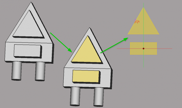
Tworzy odniesienie łącznik kształtu z wybranej bryły wewnątrz aktywnej bryły. Łącznik kształtu to obiekt odniesienia, który łączy się z krawędziami lub ścianami z innego obiektu. Można go również użyć do połączenia szkicu z jednej bryły do drugiej. Obiekt łącznik kształtu jest wyświetlany w oknie widoku 3D jako półprzezroczysty żółty.
Przykładem zastosowania może być zbudowanie skrzynki z dopasowaną pokrywą w dwóch różnych korpusach lub wykonanie otworów, które są dopasowane pomiędzy różnymi korpusami.
Zostały wybrane dwa kształty z obiektu Body.Pad004, a ich obiekty punktów odniesienia są teraz dostępne w Body001.Sketch005 jako geometria zewnętrzna dzięki Body001.ShapeBinder.
Użycie
Ogólne zastosowanie:
- Aktywuj obiekt, który ma przyjąć obiekt łącznika kształtu.
- Naciśnij przycisk
Utwórz nowy łącznik kształtu.
- Naciśnij przycisk Obiekt lub Dodaj geometrię.
- W oknie widoku 3D wybierz obiekt lub geometrię do skopiowania. Obiekt wybierze całą bryłę, Dodaj geometrię wybierze dowolny element (wierzchołek, krawędź, ściana).
- Aby usunąć wybraną geometrię, naciśnij przycisk Usuń geometrię po czym wybierz element w oknie widoku 3D. Aby anulować operację, należy ponownie nacisnąć przycisk .
- Alternatywnie, bryłę do skopiowania można wybrać przed uruchomieniem polecenia Łącznik kształtów.
- Naciśnij przycisk OK.
Przykład
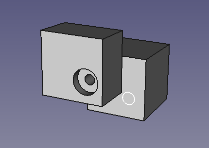
- W przykładzie wykorzystano funkcję Łącznik kształtów do wykonania otworu (z gwintem lub bez) przez więcej niż jedną bryłę. Normalnie funkcja Otwór w środowisku Projektowanie części jest ograniczona do jednej bryły. W przykładzie użyto dwóch sześcianów zwróconych do siebie, ale przesuniętych względem siebie w dowolny sposób. Otwory są tworzone za pomocą szkiców zawierających okrąg dla każdego otworu (średnica jest ignorowana przez funkcję Otwór). Po skopiowaniu szkicu do drugiego sześcianu będzie on znajdował się w tej samej pozycji w lokalnym układzie współrzędnych sześcianu. Na rysunku widać to jako białe kółko na sześcianie znajdującym się z tyłu. Nie jest to zgodne z naszymi oczekiwaniami, ponieważ otwór w tym miejscu nie byłby wyrównany do otworu w pierwszym sześcianie.
Here is how you use the ShapeBinder Feature to achieve it:
- Prepare a scene as per the above image. If you use the cubes from the Part workbench, remember that you must put them into a "body" container. Each one in a single body container. Otherwise the PartDesign functions would not work. If you build them from sketches the system should create body containers by default.
- Select the PropertiesDialog/Data Tab to move the second cube to touch the first cube with a side displacement.
- Select the PartDesign workbench
- Create a sketch on the front face of the first cube and place a circle anywhere and close the sketch
- Select the sketch in the tree and press Hole function button. Before make sure the first body is the active body (double click).
- Select a hole of appropriate size. The image above had also counterbore selected. Close the Hole function.
- Now the image should look as above. When you hide the first cube (select and press space) you can see that the hole does not reach the second cube. It will not, even when you select "Through All", or when you enter a really large distance in the Hole dialog. The hole dialog is always limited to a single body.
- Here is where our ShapeBinder comes in.
- First select the back cube. This is the target where the ShapeBinder will be added. It must be activated, so be sure it has been double-clicked.
- In the tree select the sketch we used for the hole. It's important to not activate the first body.
- Select the shapeBinder function.
- A dialog should open. In the line "Object" the name of our sketch should be visible. If you had selected the function without selecting the sketch, you could press "Object" and then select the sketch from the list. It's recommended to select it first in order to get the right one, especially if you have many sketches with automatically generated names Sketch001,.. The "Add Geometry" is not useful for us, because we want to select the whole sketch. "AddGeometry" is used if only parts should be selected.
- Press OK to close the sketch function and check that a new item has been added to the tree of the second cube.
- When you toggle the visibility of the ShapeBinder it is shown yellow in the 3D view. However it's on the wrong position, just as the white circle in the image above. That is because of the default setting for the Trace parameter.
- In the PropertyView of the ShapeBinder in the Data tab set the Trace Support parameter to true. The default was false.
- With Trace Support true, the ShapeBinder in not affected by local transformations of the target body, e.g. our translations. The shape remains exactly where the original front object shape has been. Try moving the front object around and you can see that the ShapeBinder always follows to the new position.
- Unfortunately we can not select the ShapeBinder for a Hole. Therefore we create a local sketch and use that for our hole in the second cube.
- Select the front face of the back cube and create a new sketch (click OK for the suggestion in the dialog)
- Make all geometry invisible and the ShapeBinder visible. Now you can use the external geometry function and select the circle in the shape binder. We need the center point of that circle.
- Create a new circle and put it at the center point of the ShapeBinders circle. The radius is not important. The Hole function only uses the center points of the circles (note: single points are ignored by the Hole function, we must use circles)
- Close the sketch and click Hole. Set the dialog to the same values as the initial hole and press OK.
Zrobione Teraz masz dwa połączone otwory w dwóch różnych bryłach. Jeśli zmienisz geometrię lub położenie tych otworów, oba zostaną dostosowane. Tylko gdy dodajesz nowy otwór, musisz zaktualizować szkic w drugim sześcianie dla drugiego otworu.
- Notes
- that there is another way to create a ShapeBinder: with the back cube activated click the front face of the front cube and create a new sketch. A dialog will pop up where you select "Dependent sketch". This will actually create a shape binder. You can see the Trace Support parameter in the property window. It's a few clicks less than our procedure.
- Also note that working with ShapeBinder with Sketches is only a subset of its capabilities. It's also possible to use parts of 3D geometry as seen in the example above.
Opcje
Kliknij dwukrotnie etykietę Łącznik kształtu w okienku widoku drzewa lub kliknij prawym przyciskiem myszki i wybierz Edytuj łącznik kształtu z menu kontekstowego, aby edytować jego parametry.
Właściwości
- DANELabel: nazwa nadana obiektowi, nazwa ta może być zmieniona dla wygody.
- DANETrace Support: Przy ustawieniu tej opcji na wartość true, Łącznik kształtów stosuje się do względnego rozmieszczenia części i brył. Wartość domyślna to false. Zobacz powyższy przykład, jak to działa i jak to jest używane dostępne w wersji 0.18.
Ograniczenia
- Multiple selection is not supported. The Add geometry and Remove geometry buttons need to be pressed for each single selection.
There is a workaround for multiple selection: If you select all the elements you want to have before creating the ShapeBinder, they appear in the initial list.
- A shape binder cannot serve as base feature.
- Selected geometry on a body must be contiguous.
- If the body to be copied is selected first before launching the command, or if the Object button is used, it is no longer possible to only select specific geometry elements.
- The relative placement of the target body and the copied body is not taken into account. The shape binder will adopt the same internal coordinates as the copied body. Since version 0.18 it has a new property "Trace Support", in order to switch this behavior to take into account the relative placements.
- Narzędzia struktury: Część, Grupa
- Narzędzia wspomagające: Utwórz zawartość, Nowy szkic, Edycja szkicu, Mapuj szkic na ścianę
- Narzędzia do modelowania
- Narzędzia do ustalania położenia punktów odniesienia: Utwórz punkt odniesienia, Utwórz linię odniesienia, Utwórz płaszczyznę odniesienia, Układ współrzędnych, Łącznik kształtu, Łącznik kształtów podrzędnych, Utwórz klon
- Narzędzia addytywne: Wyciągnięcie, Wyciągnij przez obrót, Wyciągnięcie przez profile, Wyciągnięcie po ścieżce, Addytywna helisa, Addytywny sześcian, Addytywny walec,Addytywna sfera, Addytywny stożek, Addytywna elipsoida, Addytywny torus, Addytywny graniastosłup, Addytywny klin
- Narzędzia subtraktywne: Kieszeń, Otwór, Rowek, Subtraktywne wyciągnięcie przez profile, Subtraktywne wyciągnięcie po ścieżce, Subtraktywna helisa, Subtraktywny sześcian, Subtraktywny walec, Subtraktywna sfera, Subtraktywny stożek, Subtraktywna elipsoida, Subtraktywny torus,Subtraktywny graniastosłup, Subtraktywny klin
- Narzędzia do transformacji: Odbicie lustrzane, Szyk liniowy, Szyk kołowy, Transformacja wielokrotna, Skaluj
- Narzędzia ulepszające: Zaokrąglenie, Fazka, Pochylenie ścian, Grubość
- Funkcje logiczne Funkcje logiczne
- Dodatki: Przenieś, Koło łańcuchowe, Koło zębate ewolwentowe, Kreator projektowania wału
- Narzędzia menu kontekstowego: Ustaw czubek, Przenieś cechę, Przenieś cechę w drzewie, Wygląd zewnętrzny, Ustaw kolor
- Jak zacząć
- Instalacja: Pobieranie programu, Windows, Linux, Mac, Dodatkowych komponentów, Docker, AppImage, Ubuntu Snap
- Podstawy: Informacje na temat FreeCAD, Interfejs użytkownika, Profil nawigacji myszką, Metody wyboru, Nazwa obiektu, Edytor ustawień, Środowiska pracy, Struktura dokumentu, Właściwości, Pomóż w rozwoju FreeCAD, Dotacje
- Pomoc: Poradniki, Wideo poradniki
- Środowiska pracy: Strona Startowa, Architektura, Assembly, CAM, Rysunek Roboczy, MES, Inspekcja, Siatka, OpenSCAD, Część, Projekt Części, Punkty, Inżynieria Wsteczna, Robot, Szkicownik, Arkusz Kalkulacyjny, Powierzchnia 3D, Rysunek Techniczny, Test Framework

