Projekt Części: Koło zębate ewolwentowe
|
|
| Lokalizacja w menu |
|---|
| Projekt części → Involute gear... |
| Środowisko pracy |
| Projekt Części |
| Domyślny skrót |
| brak |
| Wprowadzono w wersji |
| - |
| Zobacz także |
| FCGear |
Opis
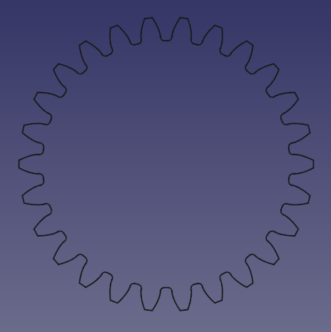
Narzędzie to pozwala na utworzenie dwuwymiarowego profilu koła zębatego. Ten profil 2D jest w pełni parametryczny i może być wyciągnięty funkcją Wyciągnięcie lub Addytywna helisa.
Bardziej szczegółowe informacje można znaleźć również na stronach Wiki: przekładnie oraz Zarys ewolwentowy
Użycie
Utworzenie profilu
- Opcjonalnie aktywuj właściwą zawartość.
- Przejdź do menu Projekt Części →
Przekładnia ewolwentowa ....
- Ustaw parametry zębatki.
- Kliknij OK.
- Jeśli koło zębate znajduje się poza aktywną zawartością: przeciągnij go i upuść do zawartości, aby zastosować dalsze funkcje, takie jak wyciągnięcie.
Utworzenie koła zębatego czołowego
- Select the gear profile in the tree.
- Press the
PartDesign Pad button.
- Set the pad's DANELength to the desired face width of the gear.
- Click OK
Create a helical gear
- Select the gear profile in the tree.
- Press the
PartDesign AdditiveHelix button.
- Choose as Axis the normal of the gear profile, that is Normal sketch axis introduced in version 0.20. (In earlier versions the Base Z axis can be used as long as the profile's plane has not been altered.)
- Choose a Height-Turns mode.
- Set the DANEHeight to the desired face width of the gear.
- To set the desired helical angle an Expressions for the DANETurns is required.
- Click the blue
icon at the right of the input field.
- Enter the following formula:
Height * tan(25°) / (InvoluteGear.NumberOfTeeth * InvoluteGear.Modules * pi), where25°is an example for the desired helical angle (also known as beta-value) andInvoluteGearis the DANEName of the profile. - Click OK to close the formula editor.
- Click the blue
- Click OK to close the task panel.
Hint: To make the helical angle an accessible parameter, use a dynamic property:
- Select the profile.
- In the Property editor activate the Show all option in the context menu.
- Again in the context menu, select Add Property. Note: this entry is only available when Show all is active.
- In the Add Property dialog:
- Choose
App::PropertyAngleas Type. - Set
Gearas Group. - Set
HelicalAngleas Name (without a space). - Click OK
- Choose
- Now a new property DANEHelical Angle (space added automatically), with an initial value of
0.0°, becomes available. - Assign the desired helical angle to the new property.
- In the formula of the DANETurns property of the AdditiveHelix, you can now reference
InvoluteGear.HelicalAngleinstead of the hard coded value of e.g.25°; again assumingInvoluteGearis the DANEName of the profile.
Properties
- Zarys zewnętrzny: Wybierz: tak lub nie.
- Wysoka dokładność: Wybierz: tak lub nie.
- Moduły: Średnica podziałki podzielona przez liczbę zębów.
- Liczba zębów: Ustawia liczbę zębów.
- Kąt przyporu: Kąt ostry między linią działania a normalną do linii łączącej środki kół zębatych. Domyślnie jest to 20 stopni
Poradniki
Jak zrobić przekładnie zębate w FreeCAD
Powiązane
- Narzędzia struktury: Część, Grupa
- Narzędzia wspomagające: Utwórz zawartość, Nowy szkic, Edycja szkicu, Mapuj szkic na ścianę
- Narzędzia do modelowania
- Narzędzia do ustalania położenia punktów odniesienia: Utwórz punkt odniesienia, Utwórz linię odniesienia, Utwórz płaszczyznę odniesienia, Układ współrzędnych, Łącznik kształtu, Łącznik kształtów podrzędnych, Utwórz klon
- Narzędzia addytywne: Wyciągnięcie, Wyciągnij przez obrót, Wyciągnięcie przez profile, Wyciągnięcie po ścieżce, Addytywna helisa, Addytywny sześcian, Addytywny walec,Addytywna sfera, Addytywny stożek, Addytywna elipsoida, Addytywny torus, Addytywny graniastosłup, Addytywny klin
- Narzędzia subtraktywne: Kieszeń, Otwór, Rowek, Subtraktywne wyciągnięcie przez profile, Subtraktywne wyciągnięcie po ścieżce, Subtraktywna helisa, Subtraktywny sześcian, Subtraktywny walec, Subtraktywna sfera, Subtraktywny stożek, Subtraktywna elipsoida, Subtraktywny torus,Subtraktywny graniastosłup, Subtraktywny klin
- Narzędzia do transformacji: Odbicie lustrzane, Szyk liniowy, Szyk kołowy, Transformacja wielokrotna, Skaluj
- Narzędzia ulepszające: Zaokrąglenie, Fazka, Pochylenie ścian, Grubość
- Funkcje logiczne Funkcje logiczne
- Dodatki: Przenieś, Koło łańcuchowe, Koło zębate ewolwentowe, Kreator projektowania wału
- Narzędzia menu kontekstowego: Ustaw czubek, Przenieś cechę, Przenieś cechę w drzewie, Wygląd zewnętrzny, Ustaw kolor
- Jak zacząć
- Instalacja: Pobieranie programu, Windows, Linux, Mac, Dodatkowych komponentów, Docker, AppImage, Ubuntu Snap
- Podstawy: Informacje na temat FreeCAD, Interfejs użytkownika, Profil nawigacji myszką, Metody wyboru, Nazwa obiektu, Edytor ustawień, Środowiska pracy, Struktura dokumentu, Właściwości, Pomóż w rozwoju FreeCAD, Dotacje
- Pomoc: Poradniki, Wideo poradniki
- Środowiska pracy: Strona Startowa, Architektura, Assembly, CAM, Rysunek Roboczy, MES, Inspekcja, Siatka, OpenSCAD, Część, Projekt Części, Punkty, Inżynieria Wsteczna, Robot, Szkicownik, Arkusz Kalkulacyjny, Powierzchnia 3D, Rysunek Techniczny, Test Framework
