Projekt Części: Subtraktywna helisa
|
|
| Lokalizacja w menu |
|---|
| Projekt Części → Utwórz cechę przez odjęcie → Subtraktywna helisa |
| Środowisko pracy |
| Projekt Części |
| Domyślny skrót |
| brak |
| Wprowadzono w wersji |
| 0.19 |
| Zobacz także |
| Addytywna helisa |
Opis
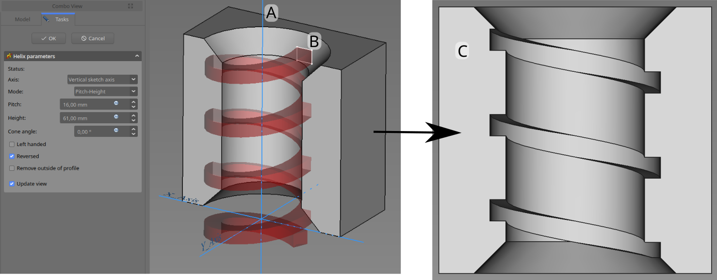
Narzędzie Subtraktywna helisa modyfikuje bryłę poprzez przesuwanie wybranego szkicu lub obiektu 2D po ścieżce spiralnej wycinającej materiał.

Profil (B) jest przesuwany wokół osi (A) w celu wytworzenia spiralnego rowka (C) w istniejącym wcześniej elemencie obrabianym.
Użycie
- Select the sketch to be swept into a helix. A face on the existing solid can alternatively be used.
- Press the
PartDesign SubtractiveHelix button.
- Set the Helix parameters (see next section).
- Inspect the Helix in the view window, to ensure that the parameters do not result in a self intersecting helix.
- Press OK.
Options
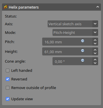
When creating a SubtractiveHelix, the Helix parameters dialogue offers several parameters specifying how the sketch should be swept.

Axis
This option specifies the axis about which the sketch is to be swept.
- Normal sketch axis: selects the normal of the sketch that runs through the sketch origin as axis. introduced in version 0.20
- Vertical sketch axis: selects the vertical sketch axis.
- Horizontal sketch axis: selects the horizontal sketch axis.
- Construction line: selects a construction line contained in the sketch used by the Helix. The drop down list will contain an entry for each construction line. The first construction line created in the sketch will be labelled Construction line 1.
- Base (X/Y/Z) axis: selects the X, Y or Z axis of the Body's Origin;
- Select reference...: allows selection in the 3D view of an edge on the Body, or a datum line.
Mode
This controls what parameters will be used to define the helix. The choices are:
- Pitch-Height-Angle: definition via the height per turn and the overall height
- Pitch-Turns-Angle: definition via the height per turn and the number of turns
- Height-Turns-Angle: definition via the overall height and the number of turns
- Height-Turns-Growth introduced in version 0.20: definition via the overall height, the number of turns and the growth of the helical radius. So a Height of zero leads to a path in form of a spiral. A Height and Growth of zero to leads to a path in form of a circle.
Pitch
The distance between turns in the helix.
Height
The height of the helix (center-center).
Turns
The number of turns in the helix. Define as Height/Pitch
Cone Angle
Angle of the cone that forms a hull around the helix. Allowable range: [-89°, +89°].
Left handed
If checked, the turning direction of helix is reversed from default clockwise to counterclockwise.
Reversed
If checked, the axis direction of helix is reversed from default.
Remove outside of profile
If checked, the result will be the intersection of the swept profile and the preexisting body.
Update view
If checked, the helix will be shown in the view, and updated automatically on every change of the parameters.
Preferences
- A subtractive helix that does not intersect the body will be visible in the preview if Tools → Edit parameters... → BaseApp → Preferences → Mod → PartDesign → SubtractiveHelixPreview is set to
true. The default for this preference istrue. introduced in version 0.20
Properties
- DANEPitch: The axial distance between two turns.
- DANEHeight: The total length of the helix (not accounting for the extent of the profile)
- DANETurns: The number of turns (does not need to be a whole number)
- DANELeft Handed: See Left Handed.
- DANEReversed: See Reversed.
- DANEAngle: The rate at which the radius of the helix increase along the axis. Allowable range: [-89°, +89°].
- DANEReference axis: The helix axis
- DANEMode: The helix input mode (pitch-height, pitch-turns, turns-height)
- DANEOutside: If true, the result will be the intersection of the swept profile and the preexisting body.
- DANEHas Been Edited: If false, the tool will propose an initial value for pitch based on the profile bounding box, so that self intersection is avoided.
- DANERefine: true or false. If set to true, cleans the solid from residual edges left by features. See Part RefineShape for more details.
- DANEProfile: Either a sketch containing a closed contour, or a face.
- DANEMidplane: Not used.
- DANEUp to face: Not used.
- DANEAllow multiple face: Not used.
- Narzędzia struktury: Część, Grupa
- Narzędzia wspomagające: Utwórz zawartość, Nowy szkic, Edycja szkicu, Mapuj szkic na ścianę
- Narzędzia do modelowania
- Narzędzia do ustalania położenia punktów odniesienia: Utwórz punkt odniesienia, Utwórz linię odniesienia, Utwórz płaszczyznę odniesienia, Układ współrzędnych, Łącznik kształtu, Łącznik kształtów podrzędnych, Utwórz klon
- Narzędzia addytywne: Wyciągnięcie, Wyciągnij przez obrót, Wyciągnięcie przez profile, Wyciągnięcie po ścieżce, Addytywna helisa, Addytywny sześcian, Addytywny walec,Addytywna sfera, Addytywny stożek, Addytywna elipsoida, Addytywny torus, Addytywny graniastosłup, Addytywny klin
- Narzędzia subtraktywne: Kieszeń, Otwór, Rowek, Subtraktywne wyciągnięcie przez profile, Subtraktywne wyciągnięcie po ścieżce, Subtraktywna helisa, Subtraktywny sześcian, Subtraktywny walec, Subtraktywna sfera, Subtraktywny stożek, Subtraktywna elipsoida, Subtraktywny torus,Subtraktywny graniastosłup, Subtraktywny klin
- Narzędzia do transformacji: Odbicie lustrzane, Szyk liniowy, Szyk kołowy, Transformacja wielokrotna, Skaluj
- Narzędzia ulepszające: Zaokrąglenie, Fazka, Pochylenie ścian, Grubość
- Funkcje logiczne Funkcje logiczne
- Dodatki: Przenieś, Koło łańcuchowe, Koło zębate ewolwentowe, Kreator projektowania wału
- Narzędzia menu kontekstowego: Ustaw czubek, Przenieś cechę, Przenieś cechę w drzewie, Wygląd zewnętrzny, Ustaw kolor
- Jak zacząć
- Instalacja: Pobieranie programu, Windows, Linux, Mac, Dodatkowych komponentów, Docker, AppImage, Ubuntu Snap
- Podstawy: Informacje na temat FreeCAD, Interfejs użytkownika, Profil nawigacji myszką, Metody wyboru, Nazwa obiektu, Edytor ustawień, Środowiska pracy, Struktura dokumentu, Właściwości, Pomóż w rozwoju FreeCAD, Dotacje
- Pomoc: Poradniki, Wideo poradniki
- Środowiska pracy: Strona Startowa, Architektura, Assembly, CAM, Rysunek Roboczy, MES, Inspekcja, Siatka, OpenSCAD, Część, Projekt Części, Punkty, Inżynieria Wsteczna, Robot, Szkicownik, Arkusz Kalkulacyjny, Powierzchnia 3D, Rysunek Techniczny, Test Framework