Basic modeling tutorial/pl: Difference between revisions
(Created page with "center|frame|Rys. 1.5 Oryginalne sześciany mogą być nadal widoczne.") |
|||
| Line 48: | Line 48: | ||
[[Image:Tutorial-normand04.jpg|center|frame|Rys. 1.4 Operacja wycięcia zachowuje swoje oryginalne obiekty ''(sześciany)'']] |
[[Image:Tutorial-normand04.jpg|center|frame|Rys. 1.4 Operacja wycięcia zachowuje swoje oryginalne obiekty ''(sześciany)'']] |
||
[[Image:Tutorial-normand05.jpg|center|frame| |
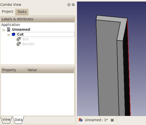
[[Image:Tutorial-normand05.jpg|center|frame|Rys. 1.5 Oryginalne sześciany mogą być nadal widoczne.]] |
||
By the way, we can add rounds to the angle so it is more realistic, using the [[Image:Part_Fillet.svg|32px]] [[Part_Fillet|Fillet]] tool. ''(Fig. 1.6)'' |
By the way, we can add rounds to the angle so it is more realistic, using the [[Image:Part_Fillet.svg|32px]] [[Part_Fillet|Fillet]] tool. ''(Fig. 1.6)'' |
||
Revision as of 19:57, 13 September 2021
| Temat |
|---|
| Wprowadzenie do modelowania |
| Poziom trudności |
| Początkujący |
| Czas wykonania |
| 15 minut |
| Autorzy |
| NormandC |
| Wersja FreeCAD |
| dowolny |
| Pliki z przykładami |
| Nie dołączono |
| Zobacz również |
| - |
Wprowadzenie
Ten Podstawowy Samouczek Modelowania pokaże Ci jak modelować żelazny kształtownik. Jedną rzeczą, którą należy wiedzieć jest to, że FreeCAD jest z założenia modularny, i tak jak w przypadku wielu innych programów CAD, zawsze jest więcej niż jeden sposób na zrobienie czegoś. Przeanalizujemy tutaj dwie metody.
Zanim zaczniemy
Pamiętaj, że FreeCAD jest wciąż we wczesnej fazie rozwoju, więc możesz nie być tak wydajny jak w przypadku innych aplikacji CAD i z pewnością napotkasz błędy lub doświadczysz awarii. FreeCAD ma teraz możliwość zapisywania plików kopii zapasowych. Liczba tych plików może być określona w oknie dialogowym preferencji. Nie wahaj się pozwolić na dwa lub trzy pliki zapasowe, dopóki nie poznasz dobrze zasad działania programu FreeCAD.
Często zapisuj swoją pracę, od czasu do czasu zapisz ją pod inną nazwą, abyś miał "bezpieczną" kopię, do której możesz wrócić, i bądź przygotowany na to, że niektóre polecenia mogą nie dać Ci oczekiwanych rezultatów.
Techniki modelowania Intro
Pierwszą (i podstawową) techniką modelowania bryłowego jest Constructive Solid Geometry (CSG). Istnieje również szczegółowe wyjaśnienie (w kontekście FreeCAD) Konstrukcyjna geometria bryły na wiki. Pracujesz z kształtami typu bryły pierwotne, takimi jak sześciany, walce, kule i stożki, aby skonstruować geometrię poprzez łączenie ich, odejmowanie jednego kształtu od drugiego lub przecinanie ich. Narzędzia te są częścią środowiska pracy Część. Możesz również stosować przekształcenia na kształtach, jak np. zaokrąglenia lub sfazowania na krawędziach. Te narzędzia również znajdują się w środowisku pracy Część.
Dostępne są też bardziej zaawansowane narzędzia. Zaczynasz od narysowania dwuwymiarowego profilu, który będziesz albo wyciągać, albo obracać.
Zacznijmy więc od próby zrobienia kilku żelaznych nóg do stołu za pomocą tych 2 metod.
Pierwsza metoda - Konstrukcyjna geometria bryły
- Zacznij od środowiska pracy Część
.
- Jeśli nie otworzyłeś nowego dokumentu FreeCAD (większość okna FreeCAD wygląda na nieaktywną), z rozwijanego menu kliknij Plik → Nowy lub kliknij przycisk
 . Utwórz nowy, pusty dokument.
 - Kliknij na przycisk
Sześcian, aby utworzyć sześcian.
- Zmień jego wymiary wybierając go w przestrzeni 3D lub klikając na zakładce Projekt po lewej stronie, a następnie,
- Kliknij na zakładkę Dane na dole i zmień wartości dla Długość, Szerokość i Wysokość na 50mm, 50 i 750 (patrz rys. 1.1) Uwaga': w czasie, gdy te rysunki były wykonywane, właściwości były uporządkowane inaczej, wysokość była pierwsza.
- Sześcian wypełnia teraz większą część widoku 3D. Kliknij na przycisk
Dopasuj wszystko, aby dopasować widok do nowo utworzonego sześcianu.
- Utwórz następny sześcian w ten sam sposób, ale z wartościami L=40, W=40 i H=750mm. Domyślnie będzie on nałożony na pierwszy. (patrz rys. 1.2)
- Odejmij teraz drugi sześcian od pierwszego. Wybierz najpierw pierwszy kształt (o nazwie Sześcian), a następnie drugi (o nazwie Sześcian001), kolejność wyboru jest ważna! (Upewnij się, że oba kształty są zaznaczone w drzewie projektu. Jedna rzecz do zapamiętania: w trybie nawigacji Inventora, Ctrl + kliknięcie nie działa w przypadku wielokrotnego zaznaczania. Przełącz Profil nawigacji myszką na wybór CAD lub Blender).
- Na pasku narzędzi środowiska pracy Część, kliknij na przycisk narzędzia
Wytnij.
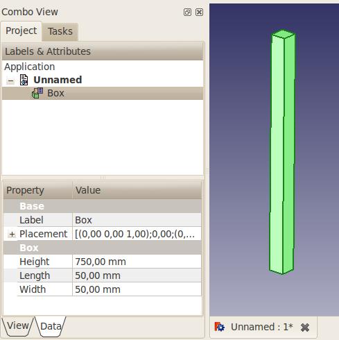
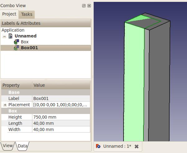
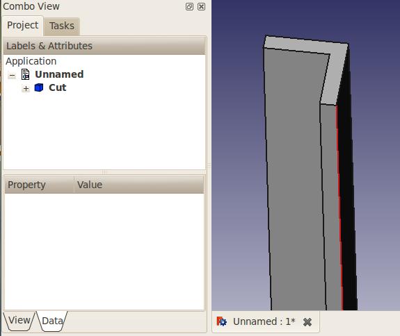
You now have your first iron angle (Fig. 1.3). You'll notice that, in the Project tab on the left, both boxes have been replaced by a "Cut" object. Actually, they're not disappeared, but rather grouped under the Cut object. Click on the + in front of it, and you'll see that both boxes are still there, but greyed out (Fig. 1.4). If you click on either of them and hit the Space bar, it will show up. The space bar toggles visibility of selected objects. (Fig. 1.5)
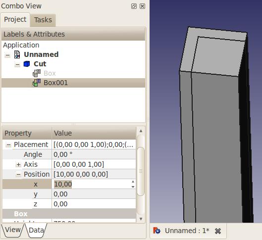
Don't want the angle oriented that way? You just need to change the placement of the Box001 shape. Select it, unhide it, and in the Data tab, click on the + in front of Placement, then expand the Position parameter, and change its X and Y coordinates. Hit Enter, hide the Box001 shape again, and your angle orientation is now different. (Fig. 1.5) You can even change either of your shapes dimensions, and the Cut object will be updated.
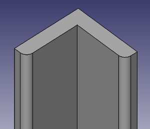
By the way, we can add rounds to the angle so it is more realistic, using the Fillet tool. (Fig. 1.6)
2nd Method - By extruding a profile
This method requires that you start by drawing a 2D profile. You need to activate the Draft workbench .
- If you haven't opened a new FreeCAD document (most of the FreeCAD window looks greyed-out), from the pull-down menu click File → New or click the
 Create a new empty document icon.
Setting the working plane
First we need to define on which working plane to draft our profile.
- Locate the toolbar displayed below. Depending on your Draft preferences, it may be below the main toolbar, to the left or to the right.
- Press the Auto button (it may be labeled "None").
- Depending on your Draft preferences, this expands a Select Plane dialog in the Tasks side panel, or a horizontal toolbar labeled "active command: Select Plane". See the Note on Draft Working Plane Button for screen captures showing the two expanded modes.
- We will leave the Offset field at a value of zero.
- Press the XY button to set the working plane to XY. This closes the Tasks panel or the expanded buttons. The "Auto" button will now be relabeled as "Top" to show it is the active plane.
Drafting the profile
- Select the
DWire (multiple-point DraftWire) tool.
- Check the "Relative" and "Filled" boxes.
- Rather than drawing the shape in the 3D view, we'll enter coordinates in the Global X, Global Y and Global Z input fields. The process is the following:
- Click in the Global X input field;
- Enter a value as listed in the bullet list below and press TAB to go to the Global Y input field;
- Enter the Global Y value and press TAB to go to the Global Z input field;
- In the Global Z field, leave the zero value and press ENTER to validate the coordinates for the point;
- Repeat for the next 5 points.
- Coordinates (X, Y, Z)
- 1st point: 0, 0, 0
- 2nd point: 50, 0, 0
- 3rd point: 0,10, 0
- 4th point: -40, 0, 0 Note: in FreeCAD 0.16, there is a bug that removes the previous point when entering the minus sign in the input field. A workaround is to enter a positive value, then place the cursor before the number and add the minus sign. (This bug is resolved in v0.17)
- 5th point: 0, 40, 0
- 6th point: -10, 0, 0
- Press the Close button to close the profile. You should now have this profile, titled DWire in the Model tab:
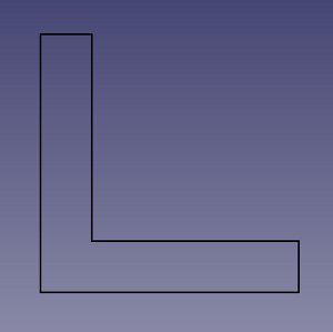
Hit the 0 (zero) key on the numerical keypad to set the view to axonometric.
Extruding the profile
Activate the Part Workbench either from the workbench selector, or from the View → Workbench → Part menu.
Click on the Extrude tool.
On the Tasks tab on the left, select the Wire object. Then enter the desired length, say 750mm. Leave the direction at Z = 1. Press OK. You should now have an Extrude object in the Model tab (fig. 1.8)
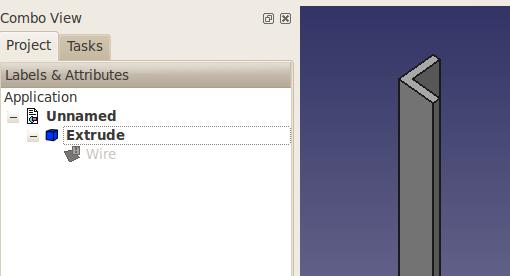
This method has a minor caveat compared to the other one: to edit the shape, you need to edit the Wire, it's not as easy to do as the previous method.
And there are a few other ways to do it too! I hope these two examples get you started. You'll sure hit some snags along the way (I did when I first learned FreeCAD, and I do have 3D CAD experience), but don't hesitate to ask questions on the FreeCAD forum!
Note on Draft Working Plane Button
The label on your button may be different, depending on your version and also on what you were doing beforehand. The button label could read: "Top", "Front", "Side", "None" or a Vector representation such as d(0.0,0.0,1.0). It can also be blank. For example:


After pressing the button, the options will be expanded into either of the following configurations.
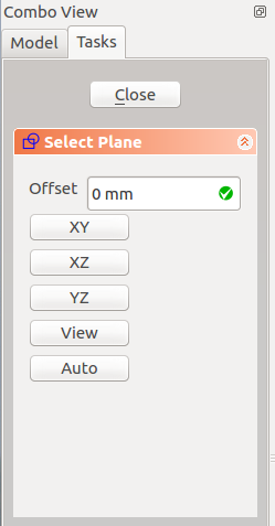

Powyższe instrukcje będą działać, bez względu na to, jaką etykietę posiada Twój przycisk.
- Bryły pierwotne: Prostopadłościan, Walec, Sfera, Stożek, Torus, Rura, Bryły pierwotne, Konstruktor kształtu
- Tworzenie i modyfikacja: Wyciągnij, Wyciągnij przez obrót, Odbicie lustrzane, Zaokrąglenie, Fazka, Utwórz ścianę z linii łamanych, Powierzchnia prostokreślna, Wyciągnięcie przez profile, Wyciągnięcie po ścieżce, Przecięcie, Przekrój poprzeczny, Odsunięcie 3D, Odsunięcie 2D, Grubość, Rzutowanie na powierzchnię, Mocowanie
- Funkcje logiczne: Utwórz złożenie, Rozbij złożenie, Filtr złożeń, Funkcje logiczne, Wytnij, Połączenie, Część wspólna, Przyłącz, Dołącz do osadzenia, Wycięcie połączenia, Funkcja logiczna rozdzielająca, Pokrój część, Krojenie, XOR
- Wymiarowanie: Wymiarowanie liniowe, Wymiarowanie kątowe, Odśwież wymiary, Usuń wymiary, Przełącz widoczność wymiaru, Przełącz widoczność wymiarów przestrzennych, Przełącz widoczność wymiarów przyrostowych
- Jak zacząć
- Instalacja: Pobieranie programu, Windows, Linux, Mac, Dodatkowych komponentów, Docker, AppImage, Ubuntu Snap
- Podstawy: Informacje na temat FreeCAD, Interfejs użytkownika, Profil nawigacji myszką, Metody wyboru, Nazwa obiektu, Edytor ustawień, Środowiska pracy, Struktura dokumentu, Właściwości, Pomóż w rozwoju FreeCAD, Dotacje
- Pomoc: Poradniki, Wideo poradniki
- Środowiska pracy: Strona Startowa, Architektura, Assembly, CAM, Rysunek Roboczy, MES, Inspekcja, Siatka, OpenSCAD, Część, Projekt Części, Punkty, Inżynieria Wsteczna, Robot, Szkicownik, Arkusz Kalkulacyjny, Powierzchnia 3D, Rysunek Techniczny, Test Framework