FEM Geometry Preparation and Meshing
| Topic |
|---|
| Finite Element Analysis |
| Level |
| Beginner |
| Time to complete |
| N/A |
| Authors |
| NewJoker |
| FreeCAD version |
| 0.21 or above |
| Example files |
| None |
| See also |
| FEM Workbench |
Background
Geometry preparation and meshing are crucial parts of preprocessing of simulations using Finite Element Method (FEM). While easily accessible simulation software connected with a CAD environment (such as the FEM Workbench in FreeCAD) makes it tempting to perform analyses on new designs right away, it is very important to remember that FEM is an advanced method and requires properly prepared geometry and mesh to provide reasonable, accurate results. The old garbage in, garbage out rule is particularly important here. There are also other crucial settings on which FEM accuracy highly depends (such as material properties and boundary conditions) but the first steps and some of the most common sources of issues are geometry preparation and meshing, discussed on this page.
Types of geometry used for FEM in FreeCAD
- Lines (wires) - used for analyses with beam elements
- Surfaces - used for analyses with shell elements
- Solids - used for analyses with solid elements
Choice of the type of geometry
While most designs consist of solids, it's often highly recommended to use wires or surfaces for FEM if the structure allows for that:
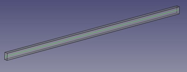
- if a part is slender (long and thin) and beam-like and has a regular cross-section of one of the currently supported beam section types (rectangular, circular or pipe) then it should be analyzed using beam elements (unless there are some specific forms of loading, response or unavoidable geometry details that invalidate this assumption). Basically, one should draw a centerline (some tips on how to extract it from existing solid geometry can be found in this forum thread) and apply proper beam section with optional rotation. There's no single rule dictating when beam elements can be used but it's often advised that the cross-section dimensions should be < 1/10 of part's length for the beam assumption to be valid.
Slender part suitable for analysis with beam elements - centerline highlighted
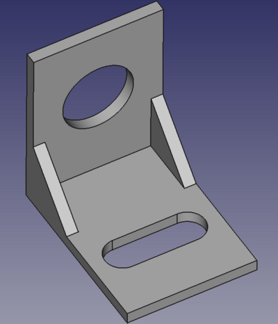
- if a part is thin-walled (such as sheet metal parts) then it should be analyzed using shell elements (unless accurate contact results are needed or some limitations of shell elements are encountered). This is very important and often overlooked. To obtain proper accuracy of results (especially when bending is involved), one needs a few elements (at least 3-5) in the thickness direction. In the case of thin-walled parts, this usually results in large meshes (especially when tetrahedrons are used since hexahedral elements can't be generated in FreeCAD) and large computational cost - high computer power requirements and long solving time. To obtain the geometry suitable for analysis with shell elements, one should draw a midsurface of the part (some tips on how to extract it from existing solid geometry can be found in this forum thread, this one and this one) and apply proper thickness. Again, there's no single rule but it's usually recommended that the thickness should be < 1/10 of a typical global dimension (length/width) for the shell assumption to be valid.
Thin-walled part suitable for analysis with shell elements - midsurface highlighted
One should remember that beam and shell elements used in CalculiX are not true beam/shell elements (they don't use the beam/shell element formulations known from literature and other software) - they are internally expanded to solids. Still, their use is recommended in the aforementioned cases.
Geometry validity
The geometry used for FEM has to be valid. Most importantly, there can't be any intersections. It's a common issue often occurring when assemblies are modeled without proper constraints between the parts. The Part SectionCut tool can help find such interferences between parts. Of course, Part Fuse may help resolve them if they are intentional. Other issues with the geometry (such as non-manifold geometries, redundant edges or faces and so on) also have to be fixed before proceeding to meshing. The Part CheckGeometry tool can be helpful but visual checks are also important. When preparing a simulation using solid elements and in doubt whether the part is really solid or just a closed shell, the aforementioned tools (Part SectionCut and Shape Content tab of the Part CheckGeometry tool output) may clarify this.
Geometry simplification
Designs prepared in CAD software are typically too detailed to be suitable for FEM simulations. In many cases, it's necessary to simplify them first. This step is often overlooked but it's very important because it can be hard to obtain a good mesh when the part is too detailed and even if such a mesh is obtained eventually, it might be very dense, leading to unreasonable solving times. Thus, one should always look at the design and try to simplify it as much as possible, leaving only those geometric features that may have a significant impact on the results (strength/stiffness) and thus can't be ignored. The following features are typically omitted:
- small fillets and chamfers,
- small holes,
- other small details,
- welds,
- bolts, threads,
- decorative elements (logos, engravings).
The Part Defeaturing tool and add-on Defeaturing Workbench can be helpful when simplifying parts for simulations.
Original bracket geometry
Bracket geometry simplified using only the Part Defeaturing tool
In the case of assemblies (more about them in one of the next sections), often some parts can be excluded from simulations and replaced with boundary conditions if they were attached to parts being analyzed. Such approach is valid if the excluded parts are significantly stiffer (in terms of structural stiffness so considering not only elasticity of the material but also geometry of the part) than the analyzed parts to which they were connected. That's because fixed boundary conditions introduce rigidity (as if the analyzed part was attached to an infinitely stiff component) and flexible supports like spring elements are not available in the FEM workbench of FreeCAD when using CalculiX (Elmer has FEM ConstraintSpring).
Geometry simplification for FEM may also mean cutting it in one of the symmetry planes to make use of the planar symmetry assumption in the analysis. This assumption is valid only when all the following aspects of the model exhibit symmetry in a given plane:
- geometry,
- loads,
- boundary conditions,
- response (one has to be careful with frequency/buckling analyses utilizing symmetry - antisymmetric mode shapes won't be obtained).
The use of symmetry (1/2, 1/4 or 1/8 of the model) is recommended whenever possible since it can highly reduce the computational cost of the analysis. Another advantage is that it eliminates some rigid body motions, making it easier to constrain the part. A symmetry boundary condition should be applied to the faces belonging to the plane of the cut:
- translation in the direction normal to the symmetry plane should be blocked for solid parts,
- translation in the direction normal to the symmetry plane and rotations other than around the axis normal to the symmetry plane should be blocked for shell and beam parts.
Applied force should be properly reduced if the symmetry plane cuts the region to which the force is applied (irrelevant when pressure load is used).
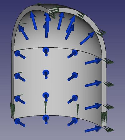
Model of 1/8 of a cylindrical pressure vessel with symmetry boundary conditions and internal pressure load
Geometry partitioning
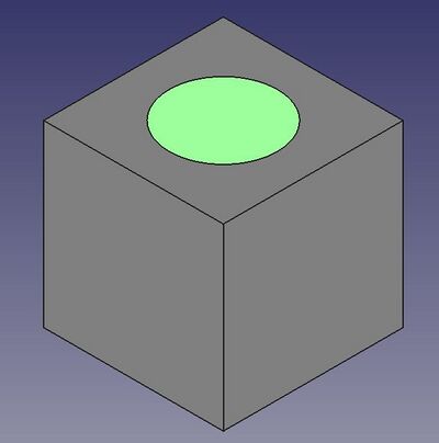
So-called partitioning is a division of the geometry into smaller segments. In other software, it's commonly used to allow hex meshing but in FreeCAD it can be useful for other reasons too. The main application of partitioning is when a load (or a boundary condition) has to be applied only to a selected region of the part's surface. The easiest way to achieve it is to create a sketch with a proper contour on that face and use the Part Boolean Fragments tool to split the face with the sketch. Another reason for partitioning is when multiple materials have to be applied to a single part (without having to use multiple parts connected with each other). Then partitioning can be done using a datum plane and Boolean Fragments tool with the Compsolid mode. Partitioning can be also used to create regions for mesh refinement.
Part with a face partition for load or boundary condition application
Assembly geometries
One of the current major limitations of the FEM workbench is that multiple meshes are not supported. In practice, this means that one cannot mesh each part of the assembly individually and then connect the parts with proper constraints for the analysis. Instead, it's necessary to create a single object containing all the parts of the assembly and mesh it. There are several different options here, all relying on Part boolean tools. The choice depends on the desired effect - whether the individual parts/volumes and their boundaries should be selectable (e.g. for material assignments or definitions of boundary conditions acting on internal faces) or not:
- Part Fuse - merges the parts, making it impossible to select them individually e.g. for material definitions,
- Part Compound - creates a compound object, making it possible to select individual parts,
- Part JoinConnect - works like Part Fuse, merges the parts, making it impossible to select them individually,
- Part BooleanFragments - works like Part Compound, making it possible to select individual parts.
It's important to mention that if the parts are touching, a continuous mesh will be created on the boolean object and no constraints will be needed for the simulation. If there's even a small gap (or an intersection within a Part Compound) between the parts, the mesh won't be continuous and constraints like tie or contact will be needed. Running a frequency analysis is a good way to reveal if the mesh is continuous or not - if the parts are not connected, the first mode shapes with deformation visualized using Warp filter will show separation - the parts will "fly away".
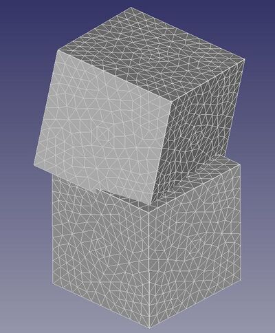
The first mode shape of a frequency analysis visualized with the Warp filter - two cubes with a small initial gap were analyzed
Selection of internal regions (faces/volumes) can be tricky. It might be needed for the application of different materials, body loads or boundary conditions (especially in thermal and electromagnetic analyses). Several ways are possible:
- enabling clipping plane for the time of selection and picking internal faces,
- hiding the boolean object, showing only one of the parts it was applied to and selecting it,
- selecting another, external object and editing the References property on the Data tab of a given analysis feature (requires manual specification of the geometric object's number).
Meshing basics
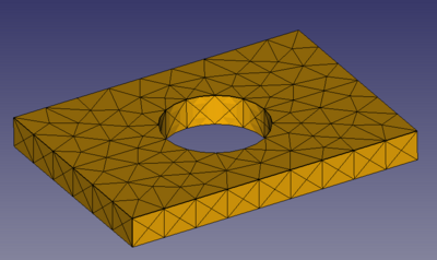
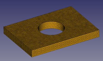
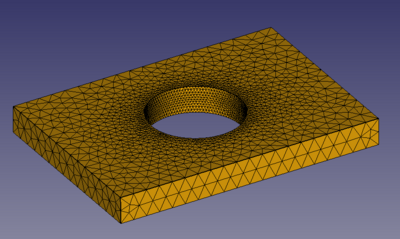
Too coarse mesh is one of the most common sources of inaccuracies and other issues in FEM. It's often a partial fault of automatic mesher settings - they typically generate very coarse, unsuitable meshes when the element size is not manually specified but left with a default value. One should always know the approximate dimensions of the part, especially the size of the smallest relevant feature (Part Measure Linear tool can help with that) and specify the proper maximum element size based on that. When meshing with Gmsh, there is also a minimum element size setting that can prevent the creation of too tiny elements around small geometric features which may lead to unnecessarily dense meshes (and sometimes even FreeCAD crashing or freezing when trying to generate such meshes). Generally speaking, it's better to start with a coarser mesh (taking less time to generate), see what it looks like (some experience is necessary) and refine it if necessary. It often makes sense to use dense mesh only around the areas of interest (locations with large stress gradients/concentrations - notches) and relatively coarse mesh away from them. This way, the number of elements can be significantly reduced, leading to shorter solving times. Local mesh refinement is defined using FEM MeshRegion.
Default, too coarse mesh
Globally refined mesh
Locally refined mesh
The choice of element type is not easy and depends on many factors but the general rule is that hexahedral and quad elements are preferable over tetrahedral and triangular ones. However, complex geometries can't be meshed with hexahedral elements and FreeCAD can't generate them at all (only quad meshes can be generated on surfaces - see this forum thread). Hexahedral elements can be imported from external meshers like Gmsh and used in the FEM workbench as shown in this video.
The choice of element order (first or second) depends on the analysis conditions but in most cases, second-order elements are preferred. This is particularly the case with triangular and tetrahedral elements - their first-order (linear) versions are normally not recommended for regular usage and they should be used only as filler elements in regions of low importance. However, since FreeCAD can't generate hexahedral elements, linear tetrahedrons can be used in some cases, if the meshes are dense enough. Especially when performing analyses with contact.
Negative Jacobians
If the above rules are followed (especially regarding geometry validity, defeaturing and element size selection), the mesh should be generated correctly. However, in some cases, the geometry can't be simplified too much, or the modeling procedure is appropriate but leads to small edges and faces anyway. Then meshing with second-order elements may fail due to negative Jacobians. The reason is that meshers have to follow the CAD model and put the mid-side nodes of second-order elements on the geometry. With more complex shapes, it may lead to elements being stretched so much that they become inverted. Jacobian is one of the most common mesh quality measures. It represents the element's deviation from the ideal shape. It becomes negative when the element turns inside out (becomes inverted) either due to large deformation during the analysis (not considered here) or because of the aforementioned meshing issues. Negative Jacobians in FreeCAD FEM might be reported by Gmsh or by CalculiX. Their locations in the mesh are highlighted when CalculiX analyses are submitted using the Run solver calculations button. The following tips can help eliminate them:
- set the Second Order Linear property of the FEMMeshGmsh object to true - this results in the mid-side nodes of second-order elements being just added in the middle of straight (initially) first-order element edges, without snapping them to the geometry and resolves the issue in most cases,
- use Netgen instead of Gmsh - Netgen is known to be less prone to negative Jacobian issues but also doesn't report them so the user may find out only when submitting the analysis,
- further reduce the element size,
- export the geometry, try meshing it in Gmsh or Netgen (NGSolve) GUI or other standalone mesher (like Salome_Meca) - those tools have additional features that can help get rid of negative Jacobians (for example, Gmsh has so-called "High-order tools"),
- use first-order elements - should be done only as a last resort since first-order tetrahedrons are known for their inaccuracy.
Regardless of those tips, it's important to emphasize once again that negative Jacobians are usually the fault of messy modeling approaches and lack of geometry preparation for analysis (especially common with STEP models downloaded from various websites). Even if the mesh is eventually generated in such cases, the results are likely to be of poor quality (recall the GIGO rule mentioned in the first paragraph). Thus, geometry clean-up and preparation for FEM should always be the priority.
Mesh convergence studies
Mesh convergence studies are recommended in all serious projects requiring accurate results. The reason is that the results can change a lot, approaching correct values when the mesh is refined. The following approach should be used:
- After obtaining the first results and noting them (usually maximum von Mises stress, von Mises stress at a given location and maximum displacement), refine the mesh (globally or better locally - with FEM MeshRegion) and rerun the simulation.
- Check the results and note their new values. If they differ significantly from the initial results, refine the mesh further and rerun the analysis.
- Repeat the process if the results still change (usually grow) significantly with mesh refinement.
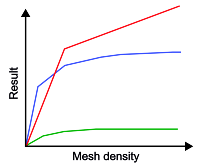
It usually helps to create a plot with a given result vs mesh density. This way it's easier to notice when the results start to converge. The acceptable difference in results between two runs is usually around a few percent (e.g. below 5%).
In some cases, it may happen that the maximum stress will be growing indefinitely regardless of how dense the mesh will be. Such a non-physical effect is known as a stress singularity. It may occur due to the following reasons:
- concentrated forces applied to solid and shell models,
- boundary conditions applied to points (individual nodes),
- sharp corners,
- contact occurring at a corner.
Typical ways of dealing with stress singularities are:
- applying loads and boundary conditions to small areas instead of points - see the section about partitioning above,
- adding small fillets to sharp corners (an exception to the rule of omitting small fillets when simplifying the geometry for FEM),
- including plasticity in material behavior to enable stress redistribution and limit the stresses to values allowed by the plasticity definition while observing the proper level of yielding (plastic strain),
- ignoring singularities and reading stresses away from them if possible (based on St. Venant’s Principle).
Typical mesh convergence plots:
- displacement (green curve) converges quickly,
- maximum stress at a notch like a hole (blue curve) needs more iterations of mesh refinement to converge,
- maximum stress at a sharp corner with a fixed boundary condition (red curve) doesn't converge at all. Stress singularity occurs and a small fillet would have to be added and the connection would have to be modeled in more realistic, flexible way to avoid this behavior.
- Materials: Solid, Fluid, Nonlinear mechanical, Reinforced (concrete); Material editor
- Element geometry: Beam (1D), Beam rotation (1D), Shell (2D), Fluid flow (1D)
Constraints
- Electromagnetic: Electrostatic potential, Current density, Magnetization
- Geometrical: Plane rotation, Section print, Transform
- Mechanical: Fixed, Displacement, Contact, Tie, Spring, Force, Pressure, Centrif, Self weight
- Thermal: Initial temperature, Heat flux, Temperature, Body heat source
- Overwrite Constants: Constant vacuum permittivity
- Solve: CalculiX Standard, Elmer, Mystran, Z88; Equations: Deformation, Elasticity, Electrostatic, Electricforce, Magnetodynamic, Magnetodynamic 2D, Flow, Flux, Heat; Solver: Solver control, Solver run
- Results: Purge, Show; Postprocessing: Apply changes, Pipeline from result, Warp filter, Scalar clip filter, Function cut filter, Region clip filter, Contours filter, Line clip filter, Stress linearization plot, Data at point clip filter, Filter function plane, Filter function sphere, Filter function cylinder, Filter function box
- Additional: Preferences; FEM Install, FEM Mesh, FEM Solver, FEM CalculiX, FEM Concrete; FEM Element Types
- Getting started
- Installation: Download, Windows, Linux, Mac, Additional components, Docker, AppImage, Ubuntu Snap
- Basics: About FreeCAD, Interface, Mouse navigation, Selection methods, Object name, Preferences, Workbenches, Document structure, Properties, Help FreeCAD, Donate
- Help: Tutorials, Video tutorials
- Workbenches: Std Base, Arch, Assembly, CAM, Draft, FEM, Inspection, Mesh, OpenSCAD, Part, PartDesign, Points, Reverse Engineering, Robot, Sketcher, Spreadsheet, Start, Surface, TechDraw, Test Framework, Web
- Hubs: User hub, Power users hub, Developer hub
