Rysunek Roboczy: Przytnij
|
|
| Lokalizacja w menu |
|---|
| Modyfkacja → Przytnij |
| Środowisko pracy |
| Rysunek Roboczy, Architektura |
| Domyślny skrót |
| T R |
| Wprowadzono w wersji |
| - |
| Zobacz także |
| Part: Wyciągnij |
Opis
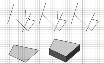
Narzędzie Przytnij przycina lub wydłuża Linie i Polilinie tak, że ich koniec znajduje się na przecięciu z inną linią lub krawędzią.
Przedłużony odcinek linii, następnie przycięty odcinek linii. Powierzchnia wyciągnięta w bryłę
Przytnij lub rozszerz
Użycie
Options
The modifier keys mentioned here can be changed. See Draft Preferences.
- The solution with the largest length determines the default direction of the command. Hold Alt to invert this direction.
- Hold Shift to restrict the operation to the current segment of a Draft Wire.
Here is an example to explain the modifier keys. The left edge or the bottom edge of the U-shaped wire was extended. All Draft Snaps were turned off.
- Wciśnij klawisze X, Y lub Z, aby zablokować punkt na danej osi.
- Przytrzymaj klawisz Shift, aby ograniczyć operację do bieżącego odcinka i nie wybierać innego.
- W przypadku trybu wyciągnięcia, przytrzymaj klawisz Shift, aby wyciąć ścianę w kierunku, który nie jest kierunkiem normalnym.
- Przytrzymaj klawisz Alt podczas przycinania, by odwrócić kierunek operacji, to znaczy, że drugi koniec odcinka zostanie ucięty.
Extrude
Usage
See also: Draft Snap and Draft Constrain.
- It can be helpful to first change the Draft working plane so that it is not coplanar with the face you want to extrude.
- Optionally select a single face or an object with a single face.
- There are several ways to invoke the command:
- Press the
Draft Trimex button.
- Select the Modification →
Trimex option from the menu.
- Use the keyboard shortcut: T then R.
- Press the
- If you have not yet selected an object or a face: select an object with a single face in the 3D view.
- The Trimex task panel opens. See Options for more information.
- To define the extrusion direction and distance do one of the following:
Options
The modifier key mentioned here can be changed. See Draft Preferences.
- Hold Shift to extrude in a direction that is not parallel to the normal of the face.
Preferences
See also: Preferences Editor and Draft Preferences.
- To change the number of decimals used for the input of the distance: Edit → Preferences... → General → Units → Units settings → Number of decimals.
Tworzenie skryptów
Zobacz również: Dokumentacja API generowana automatycznie oraz
Podstawy pisania skryptów dla FreeCAD.
Dla narzędzia Przytnij nie ma dostępnego interfejsu programistycznego. Zobacz narzędzie Część: Wyciągnij do wyciągania powierzchni i innych kształtów.
extrusion = extrude(obj, vector, solid=False)
objis the object to be extruded.vectoris the extrusion direction and distance.- If
solidisTruea solid is created instead of a shell. extrusionis returned with the created object.
Example:
import FreeCAD as App
import Draft

doc = App.newDocument()

rectangle = Draft.make_rectangle(1500, 500)
doc.recompute()

vector = App.Vector(0, 0, 300)
solid = Draft.extrude(rectangle, vector, solid=True)
doc.recompute()
- Kreślenie: Linia, Polilinia, Zaokrąglenie, Łuk, Łuk przez 3 punkty, Okrąg, Elipsa, Wielokąt foremny, Krzywa złożona, Krzywa Bezier'a, Punkt, Łącznik ścian, Kształt z tekstu, Kreskowanie, Prostokąt
- Adnotacje: Adnotacja wieloliniowa, Wymiarowanie, Etykieta, Edytor stylów adnotacji, Widżet skali anotacji
- Modyfikacja: Przesuń, Obróć, Skala, Odbicie lustrzane, Odsunięcie, Przytnij, Rozciągnij, Klonuj, Szyk, Szyk biegunowy, Szyk kołowy, Szyk po ścieżce, Szyk powiązań po ścieżce, Szyk z punktów, Szyk powiązań w punktach, Edycja, Podświetl element podrzędny, Połącz, Rozdziel, Ulepsz kształt, Rozbij obiekt na elementy, Polilinia na krzywą złożoną, Rysunek Roboczy do szkicu, Nachylenie, Obróć wymiar, Widok 2D kształtu
- Tacka narzędziowa: Wybór płaszczyzny, Ustaw styl, Przełącz tryb konstrukcyjny, Grupowanie automatyczne
- Przyciąganie: Przełącz przyciąganie, Przyciągnij do punktu końcowego, Przyciągnij do punktu środkowego, Przyciągnij do środka, Przyciągnij do kąta, Przyciąganie do punktu przecięcia, Przyciągnij prostopadle, Rozszerz, Przyciągnij równolegle, Przyciągnij specjalnie, Przyciąganie do najbliższego, Przyciągnij ortogonalnie, Przyciągnij do siatki, Przyciągnij do płaszczyzny roboczej, Przyciągnij do wymiaru, Pokaż / ukryj siatkę
- Różności: Zastosuj bieżący styl, Warstwa, Zarządzaj warstwami, Dodaj grupę o nazwie, Dodaj do grupy, Wybierz grupę, Dodaj do grupy konstrukcyjnej, Przełącz tryb wyświetlania, Pośrednia płaszczyzna robocza, Ulecz, Przełącz tryb kontynuacji, Pokaż przybornik przyciągania
- Dodatkowe:: Wiązania, Wypełnienie wzorem, Preferencje, Ustawienia Importu i Eksportu, DXF/DWG, SVG, OCA, DAT
- Menu podręczne:
- Kontener warstwy: Połącz duplikaty warstw, Dodaj warstwę
- Warstwa: Aktywuj warstwę, Zaznacz zawartość warstwy
- Pośrednia płaszczyzna robocza: Zapisz ujęcie widoku, Zapisz stan obiektów
- Jak zacząć
- Instalacja: Pobieranie programu, Windows, Linux, Mac, Dodatkowych komponentów, Docker, AppImage, Ubuntu Snap
- Podstawy: Informacje na temat FreeCAD, Interfejs użytkownika, Profil nawigacji myszką, Metody wyboru, Nazwa obiektu, Edytor ustawień, Środowiska pracy, Struktura dokumentu, Właściwości, Pomóż w rozwoju FreeCAD, Dotacje
- Pomoc: Poradniki, Wideo poradniki
- Środowiska pracy: Strona Startowa, Architektura, Assembly, CAM, Rysunek Roboczy, MES, Inspekcja, Siatka, OpenSCAD, Część, Projekt Części, Punkty, Inżynieria Wsteczna, Robot, Szkicownik, Arkusz Kalkulacyjny, Powierzchnia 3D, Rysunek Techniczny, Test Framework

