FEM MeshGmshFromShape
This documentation is not finished. Please help and contribute documentation.
GuiCommand model explains how commands should be documented. Browse Category:UnfinishedDocu to see more incomplete pages like this one. See Category:Command Reference for all commands.
See WikiPages to learn about editing the wiki pages, and go to Help FreeCAD to learn about other ways in which you can contribute.
|
|
| Menu location |
|---|
| Mesh → FEM mesh from shape by Gmsh |
| Workbenches |
| FEM |
| Default shortcut |
| None |
| Introduced in version |
| - |
| See also |
| FEM tutorial |
Description
For a finite elements analysis the geometry needs to be discretized into a FEM Mesh. This command uses the program Gmsh (which needs to be installed on the system) for calculating the mesh.
Gmsh is bundled with the FreeCAD installation binaries. Alternatively you can install it separately from FreeCAD and then use the menu Edit → Preferences → FEM → Gmsh to set the path to the gmsh.exe.
Usage
- Select the shape you want to analyze. For volume FEM this needs to be a solid or compsolid. A compsolid is necessary if your part is made from multiple materials. (A compsolid can be created with the BooleanFragments command.)
- Press the
FEM MeshGmshFromShape button.
- Select the Mesh →
FEM mesh from shape by Gmsh option from the menu.
- Press the
- Optionally edit the minimal and maximal element size. (Autodetection works fine unless you apply complicated boundary conditions.)
- Click the Apply button and wait for the computation of the mesh to complete
- Close the task. You now should see a new FEMMeshGMSH object in your active analysis container.
After the mesh has been crated you can change its properties using the property editor. After you changed a property, you must reopen the Gmsh dialog again and click the Apply button. (You can leave the dialog open while changing properties.)
Properties
- DataAlgorithm2D: The algorithm to create 2D meshes. The different algorithms are explained here. For Delaunay, see Delaunay triangulation.
- DataAlgorithm3D: The algorithm to create 3D meshes. The different algorithms are explained here.
- DataCharacteristic Length Max: The maximal size of the mesh elements. If set to 0.0, the size will be set automatically. This property can also be changed in the Gmsh dialog in the field Max element size.
- DataCharacteristic Length Min: The minimal size of the mesh elements. If set to 0.0, the size will be set automatically. This property can also be changed in the Gmsh dialog in the field Min element size.
- DataCoherence Mesh:
- true (default); duplicate mesh nodes will be removed
- false
- DataElement Dimension: The dimension of the mesh elements. This property can also be changed in the Gmsh dialog in the field Mesh element dimension.
- From Shape (default); the dimension will be determined from the dimension of the object that is meshed
- 1D
- 2D
- 3D
- DataElement Order: The mesh element order. This property can also be changed in the Gmsh dialog in the field Mesh order. introduced in version 0.20
- 1st
- 2nd (default)
- DataGeometrical Tolerance: The geometrical tolerance for the mesh to match the object edges. The default 0.0 means that Gmsh's default of 1e-8 is used.
- DataGroups Of Nodes: All nodes and not only the elements will be saved for each physical mesh group. Physical groups are collections of mesh entities (points, curves, surfaces and volumes). They and are identified by their dimension and by a tag. For example a mesh of the same object region is internally tagged the same. So all surfaces of this region will form one physical group.
- DataHigh Order Optimize: If and how meshes with DataElement Order = 2nd are optimized. The optimization is done by a deformation of the element borders.
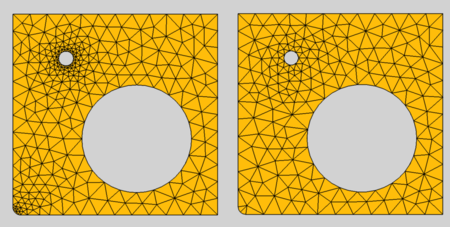
introduced in version 0.20 Gmsh supports different optimization algorithms. Elastic is an algorithm in which the mesh elements are treated as a collection of deformable viscoelastic solids. 1st order meshes cannot be optimized because their element borders are linear an cannot be deformed. - DataMesh Size From Curvature introduced in version 0.20: The number of mesh elements per times the radius of the curvature. To get a finer mesh at small corners or holes, this value can be increased for better results
Effect of Mesh Size From Curvature'; left: set to 12, right: deactivated
- DataSecond Order Linear: Option if second order nodes (if DataElement Order set to 2nd) and/or mesh refinement points are created by linear interpolation.
- true; linear interpolation is used
- false (default); curvilinear interpolation is used
Notes
Nonpositive Jacobians
When you get a meshing erro about nonpositive Jacobians, you can try out the following strategies:
- Set DataSecond Order Linear to true but keep DataElement Order at 2nd.
- Set DataElement Order to 1st.
- Use a smaller element size by reducing the DataCharacteristic Length Max.
Mesh Growth
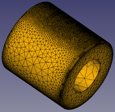
At edges and small geometric entities the mesh has to be smaller than in areas without edges. So the mesh element size grows away from edges. The growing strategy of Gmsh is to grow between edges with different sizes. So the growing fails when an area has the same sized edges like for example this tube:
Failing mesh growing because the cylindrical area is surrounded be the same edges
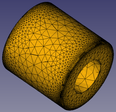
To enable a sensible mesh growing, you must in this case add an edge to the area. In the example this would be a circle in the middle of the cylinder. The circle is added as part of a BooleanFragments compound (to form a CompSolid), see the project file of the example.
Sensible mesh growing due to the additional edge in the middle of the cylindrical aread
- Materials: Solid, Fluid, Nonlinear mechanical, Reinforced (concrete); Material editor
- Element geometry: Beam (1D), Beam rotation (1D), Shell (2D), Fluid flow (1D)
Constraints
- Electromagnetic: Electrostatic potential, Current density, Magnetization
- Geometrical: Plane rotation, Section print, Transform
- Mechanical: Fixed, Displacement, Contact, Tie, Spring, Force, Pressure, Centrif, Self weight
- Thermal: Initial temperature, Heat flux, Temperature, Body heat source
- Overwrite Constants: Constant vacuum permittivity
- Solve: CalculiX Standard, Elmer, Mystran, Z88; Equations: Deformation, Elasticity, Electrostatic, Electricforce, Magnetodynamic, Magnetodynamic 2D, Flow, Flux, Heat; Solver: Solver control, Solver run
- Results: Purge, Show; Postprocessing: Apply changes, Pipeline from result, Warp filter, Scalar clip filter, Function cut filter, Region clip filter, Contours filter, Line clip filter, Stress linearization plot, Data at point clip filter, Filter function plane, Filter function sphere, Filter function cylinder, Filter function box
- Additional: Preferences; FEM Install, FEM Mesh, FEM Solver, FEM CalculiX, FEM Concrete; FEM Element Types
- Getting started
- Installation: Download, Windows, Linux, Mac, Additional components, Docker, AppImage, Ubuntu Snap
- Basics: About FreeCAD, Interface, Mouse navigation, Selection methods, Object name, Preferences, Workbenches, Document structure, Properties, Help FreeCAD, Donate
- Help: Tutorials, Video tutorials
- Workbenches: Std Base, Arch, Assembly, CAM, Draft, FEM, Inspection, Mesh, OpenSCAD, Part, PartDesign, Points, Reverse Engineering, Robot, Sketcher, Spreadsheet, Surface, TechDraw, Test Framework
- Hubs: User hub, Power users hub, Developer hub


