Arch Structure/pl: Difference between revisions
(Created page with "==Właściwości==") |
(Created page with "* {{PropertyData|Narzędzie}}: opcjonalna ścieżka wyciągnięcia, która może być dowolnym typem polilinii. Jeśli ta właściwość jest pusta, wyciąganie będzie proste i nastąpi w kierunku określonym przez właściwość Normalnej. * {{PropertyData|Normalna}}: określa kierunek, w którym będzie wyciągana podstawowa powierzchnia tej konstrukcji. Jeśli ta właściwość zostanie zachowana jako (0,0,0), kierunek zostanie automatycznie ustawiony na kierunek nor...") |
||
| Line 53: | Line 53: | ||
===Dane=== |
===Dane=== |
||
* {{PropertyData|Narzędzie}}: opcjonalna ścieżka wyciągnięcia, która może być dowolnym typem polilinii. Jeśli ta właściwość jest pusta, wyciąganie będzie proste i nastąpi w kierunku określonym przez właściwość Normalnej. |
|||
* {{PropertyData|Tool}}: an optional extrusion path, which can be any type of wire. If this property is empty, the extrusion will be straight, and happen in the direction given by the Normal property |
|||
* {{PropertyData|Normalna}}: określa kierunek, w którym będzie wyciągana podstawowa powierzchnia tej konstrukcji. Jeśli ta właściwość zostanie zachowana jako (0,0,0), kierunek zostanie automatycznie ustawiony na kierunek normalny do podstawowej powierzchni. |
|||
* {{PropertyData|Normal}}: specifies the direction in which the base face of this structure will be extruded. If this property is kept to (0,0,0), the direction will be automatically set to the normal direction of the base face. |
|||
* {{PropertyData| |
* {{PropertyData|Twórca ścian}}: określa rodzaj algorytmu generacji powierzchni do zastosowania w celu zbudowania profilu. Wybory to None, Simple, Cheese i Bullseye. |
||
* {{PropertyData| |
* {{PropertyData|Długość}}: określa długość konstrukcji. Jest to używane tylko wtedy, gdy konstrukcja nie jest oparta na profilu. |
||
* {{PropertyData| |
* {{PropertyData|Szerokość}}: określa szerokość konstrukcji. Jest to używane tylko wtedy, gdy konstrukcja nie jest oparta na profilu. |
||
* {{PropertyData|Wysokość}}: określa wysokość konstrukcji lub długość wyciągania w przypadku bazowania na profilu. Jeśli nie podano wysokości, a konstrukcja znajduje się w obiekcie [[Arch_Floor/pl|Piętro Architektoniczne]] ze zdefiniowaną wysokością, konstrukcja automatycznie przyjmie wartość wysokości piętra. |
|||
* {{PropertyData|Height}}: specifies the height of the structure, or the extrusion length when based on a profile. If no height is given, and the structure is inside an [[Arch_Floor|Arch Floor]] object with its height defined, the structure will automatically take the value of the floor height. |
|||
* {{PropertyData| |
* {{PropertyData|Odsunięcie węzłów}}: określa opcjonalne przesunięcie między linią środkową a linią węzłów. |
||
=== View === |
=== View === |
||
Revision as of 09:24, 31 March 2024
|
|
| Lokalizacja w menu |
|---|
| Architektura → Narzędzi konstrukcyjne → Konstrukcja |
| Środowisko pracy |
| Architektura |
| Domyślny skrót |
| S T |
| Wprowadzono w wersji |
| - |
| Zobacz także |
| Ściana, Zbrojenie |
Opis
Narzędzie Konstrukcja umożliwia budowanie elementów konstrukcyjnych, takich jak kolumny lub belki, poprzez określenie ich szerokości, długości i wysokości lub opierając się na profilu 2D (powierzchni, linii lub szkicu).
Jeśli nie podano profilu, dostępny jest zestaw ustawień wstępnych umożliwiających szybkie utworzenie elementu konstrukcyjnego na podstawie wstępnie zdefiniowanego profilu standardowego.
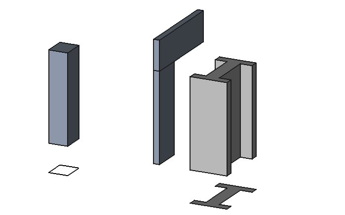
Kolumna oparta na profilu podstawowym 2D. Kolumna i belka zdefiniowane przez ich wysokość, długość i szerokość, bez profilu podstawowego. Konstrukcja metalowa oparta na powierzchni 2D.
Użycie
- Wybierz kształt 2D (obiekt środowiska Rysunek Robocy, powierzchnia lub szkic) (opcjonalnie).
- Naciśnij przycisk
Konstrukcja, lub użyj skrótu S a następnie T.
- Dostosuj właściwości według potrzeb.
Opcje
- Gdy nie jest wybrany żaden podstawowy obiekt 2D, narzędzie do tworzenia konstrukcji ma 2 tryby rysowania: Kolumna i belka:
 ** W trybie kolumny, zostaniesz poproszony o wybranie punktu na ekranie lub wprowadzenie współrzędnych. Nowy obiekt konstrukcji zostanie umieszczony w tym punkcie.
 ** W trybie belki, zostaniesz poproszony o wybranie dwóch punktów na ekranie lub wprowadzenie współrzędnych. Nowy obiekt konstrukcji będzie rozpięty między tymi dwoma punktami.
- Elementy konstrukcji mają wspólne właściwości i zachowania dla wszystkich Komponentów Architektonicznych.
- Wysokość, szerokość i długość obiektu konstrukcji można dostosować po jej utworzeniu.
- Naciśnij Esc lub przycisk Anuluj, aby przerwać bieżące polecenie.
- Podwójne kliknięcie na konstrukcji w widoku drzewa po jej utworzeniu pozwala wejść w tryb edycji i uzyskać dostęp i modyfikować jej obiekty dołączone i odejmowane.
- W trybie edycji można również dodać układy osi do elementu konstrukcyjnego. Dodając jeden układ osi, element strukturalny zostanie skopiowany raz na każdą oś układu. Dodając dwa układy osi, element konstrukcyjny zostanie skopiowany raz na każdym przecięciu się obu układów.
Właściwości
Dane
- DANENarzędzie: opcjonalna ścieżka wyciągnięcia, która może być dowolnym typem polilinii. Jeśli ta właściwość jest pusta, wyciąganie będzie proste i nastąpi w kierunku określonym przez właściwość Normalnej.
- DANENormalna: określa kierunek, w którym będzie wyciągana podstawowa powierzchnia tej konstrukcji. Jeśli ta właściwość zostanie zachowana jako (0,0,0), kierunek zostanie automatycznie ustawiony na kierunek normalny do podstawowej powierzchni.
- DANETwórca ścian: określa rodzaj algorytmu generacji powierzchni do zastosowania w celu zbudowania profilu. Wybory to None, Simple, Cheese i Bullseye.
- DANEDługość: określa długość konstrukcji. Jest to używane tylko wtedy, gdy konstrukcja nie jest oparta na profilu.
- DANESzerokość: określa szerokość konstrukcji. Jest to używane tylko wtedy, gdy konstrukcja nie jest oparta na profilu.
- DANEWysokość: określa wysokość konstrukcji lub długość wyciągania w przypadku bazowania na profilu. Jeśli nie podano wysokości, a konstrukcja znajduje się w obiekcie Piętro Architektoniczne ze zdefiniowaną wysokością, konstrukcja automatycznie przyjmie wartość wysokości piętra.
- DANEOdsunięcie węzłów: określa opcjonalne przesunięcie między linią środkową a linią węzłów.
View
- WIDOKNodes Type: The type of structural nodes of this object, linear or area.
- WIDOKShow Nodes: Shows or hides the structural nodes.
Presets
The Structure tool also features a series of presets that allow to quickly build standard metallic profiles or precast concrete elements.
Some presets for steel structures
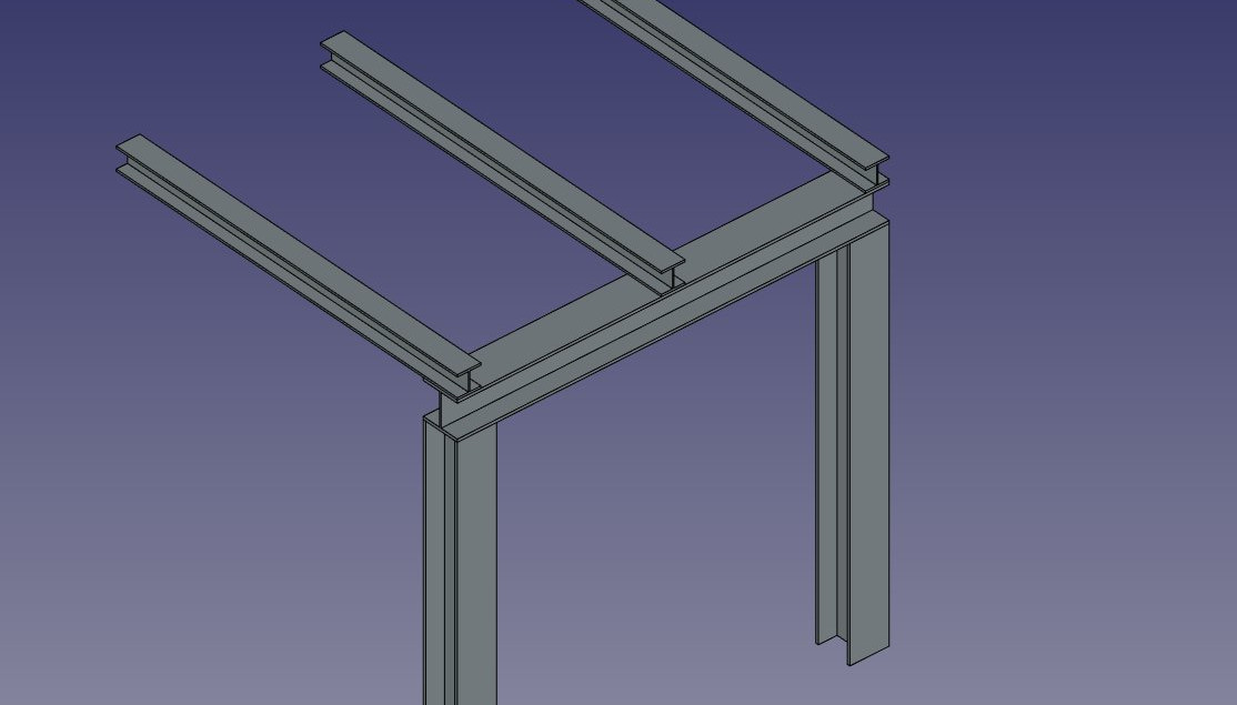
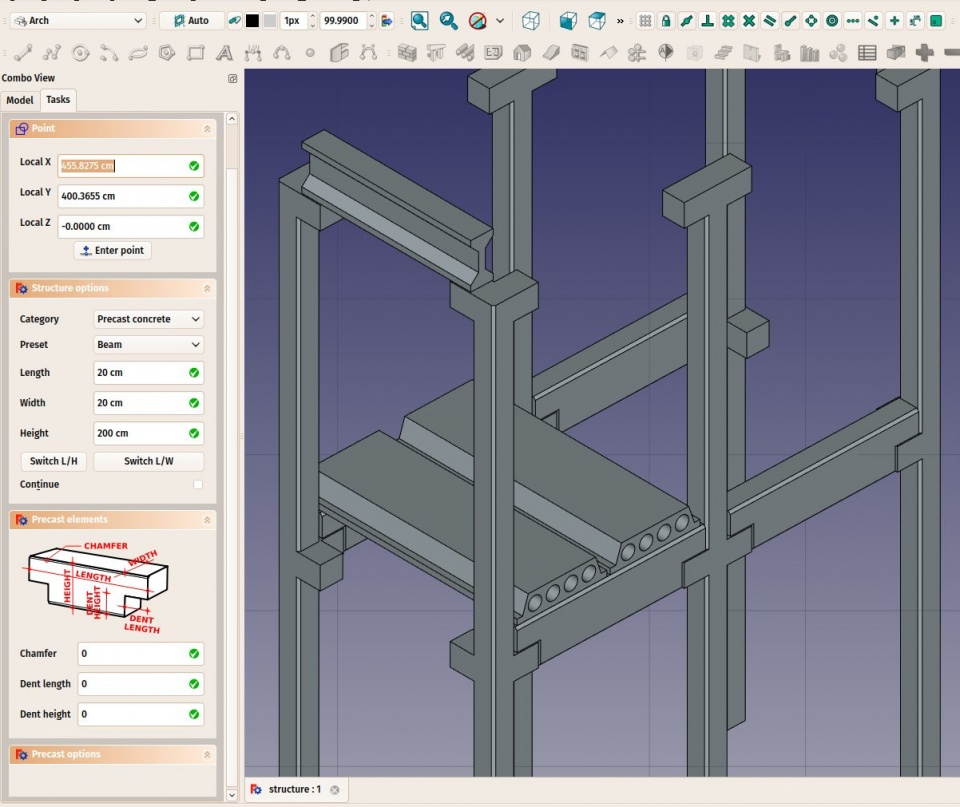
The presets are obtained by choosing a Category from the structure options panel. Available categories are Precast concrete or any of the industry-standard metallic profiles such as HEA, HEB or INP. For each of these categories, a number of presets are available. Once a preset is chosen, its individual parameters such as Length, Width or Height can be adjusted. However, for metallic profiles, the profile size is set by the preset and cannot be changed.
The Switch L/H button can be used to switch Length and Height values, and therefore building a horizontal beam rather than a vertical column.
Some presets for precast concrete structures
Structural nodes
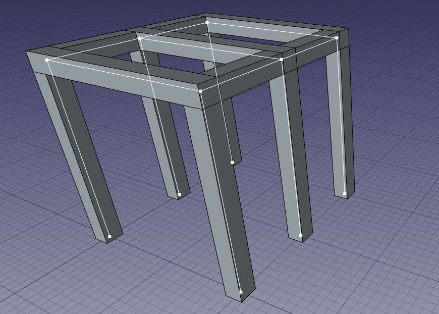
Structural objects also have the ability to display structural nodes. Structural nodes are a sequence of 3D points stored in a "Nodes" property. By switching the "Show Nodes" view property on/off, one can see the structural nodes of a structural element:
Structural nodes made visible for a set of structures
- Nodes are calculated and updated automatically, as long as you don't modify them manually. If you did, they won't be updated if the shape of the structural object changes, unless you use the "Reset nodes" tool below.
- Arch structures can have not only linear nodes, but also planar nodes. For this, 1- There must be at least 3 vectors in the "Nodes" property of the object, 2- the "NodesType" property of their ViewObject must be set to "Area".
- When the nodes calculation is automatic (that is, if you never touched them manually), when setting the Role property of a structure to "Slab", it will automatically become a planar node (there will be more than 3 vectors and the NodesType will be set to "Area").
- When editing a structure object (double-click), a couple of node tools are available in the task view:
- Reset the nodes to automatic calculation, in case you modified them manually
- Edit the nodes graphically, works the same way as Draft Edit
- Extend the nodes of the edited object until it touches the node of another object
- Make the node of this object and another one coincident
- Toggle the display of all nodes of all structural objects of the document on/off
Scripting
See also: Arch API and FreeCAD Scripting Basics.
The Structure tool can be used in macros and from the Python console by using the following function:
Structure = makeStructure(baseobj=None, height=None)
Structure = makeStructure(baseobj=None, length=None, width=None, height=None, name="Structure")
- Creates a
Structureobject from the givenbaseobj, which is a closed profile, and the given extrusionheight.- If no
baseobjis given, you can provide the numerical values for thelength,width, andheightto create a block structure. - The
baseobjcan also be any existing solid object.
- If no
Example:
import FreeCAD, Draft, Arch

Rect = Draft.makeRectangle(200, 300)
Structure1 = Arch.makeStructure(Rect, height=2000)
FreeCAD.ActiveDocument.recompute()

Structure2 = Arch.makeStructure(None, length=500, width=1000, height=3000)
Draft.move(Structure2, FreeCAD.Vector(2000, 0, 0))
FreeCAD.ActiveDocument.recompute()
- Elementy: Mury, Konstrukcja, ściana kurtynowa, Okna, Drzwi, Dach, Kubatura, Schody, Wyposażenie, Ramy, Ogrodzenie, Kratownica, Profil, Rura, Kształtka
- Zbrojenie: Pręty zbrojeniowe proste, Pręty zbrojeniowe typu U, Pręty zbrojeniowe typu L, Strzemiona, Strzemiona, Pręty zbrojeniowe spiralne, Zbrojenie słupów, Zbrojenie belek, Zbrojenie płyt stropowych, Zbrojenie stóp fundamentowych, Pręt zbrojeniowy
- Panels: Panel, Panelizacja do cięcia, Arkusz panela, Zagnieżdżanie
- Materiał: Wybór materiału, Materiał złożony
- Organizacja: Część budowli, Projekt, Teren, Budowla, Piętro, Odniesienie, Płaszczyzna przekroju, Obmiar
- Osie: Osie, Układ osi, Siatka
- Modifikacja: Płaszczyzna cięcia, Komponent dodaj, Komponent usuń, Przegląd
- Narzędzia: Komponent, Klonuj komponent, Podziel siatkę, Siatka na kształt, Zaznacz siatki nie bryłowe, Usuń kształt., Zamknij otwory, Połącz ściany, Sprawdź, Przełącz flagę Brep IFC, Trzy widoki, Arkusz kalkulacyjny IFC, Przełącz widoczność odjęcia
- Dodatkowe: Preferencje, Ustawienia Importu i Eksportu (IFC, DAE, OBJ, JSON, 3DS); SHP), Architektura: API
- Jak zacząć
- Instalacja: Pobieranie programu, Windows, Linux, Mac, Dodatkowych komponentów, Docker, AppImage, Ubuntu Snap
- Podstawy: Informacje na temat FreeCAD, Interfejs użytkownika, Profil nawigacji myszką, Metody wyboru, Nazwa obiektu, Edytor ustawień, Środowiska pracy, Struktura dokumentu, Właściwości, Pomóż w rozwoju FreeCAD, Dotacje
- Pomoc: Poradniki, Wideo poradniki
- Środowiska pracy: Strona Startowa, Architektura, Assembly, CAM, Rysunek Roboczy, MES, Inspekcja, Siatka, OpenSCAD, Część, Projekt Części, Punkty, Inżynieria Wsteczna, Robot, Szkicownik, Arkusz Kalkulacyjny, Powierzchnia 3D, Rysunek Techniczny, Test Framework


