Architektura: Teren
|
|
| Lokalizacja w menu |
|---|
| Architektura → Teren |
| Środowisko pracy |
| Architektura |
| Domyślny skrót |
| S I |
| Wprowadzono w wersji |
| - |
| Zobacz także |
| Piętro, Budowla |
Opis
Teren środowiska Architektura to specjalny obiekt łączący właściwości standardowego obiektu grupy FreeCAD i obiektów Architektury. Jest szczególnie odpowiedni do reprezentowania całego terenu projektowego lub terenu. W pracy architektonicznej opartej na formacie IFC jest głównie używany do organizacji modelu, zawierając w sobie budynki. Teren jest również wykorzystywany do zarządzania i wyświetlania fizycznego terenu oraz może obliczać objętości ziemi do dodania lub usunięcia.
Użycie
- Opcjonalnie wybierz jeden lub więcej obiektów, które mają być zawarte w nowym terenie.
- Naciśnij przycisk
Teren lub naciśnij klawisze S, a następnie I.
Opcje
- Po utworzeniu terenu możesz dodać do niego obiekty, przeciągając je i upuszczając w widoku drzewa lub korzystając z przycisku
Połącz obiekty. To określa jedynie, które obiekty są częścią danego terenu, i nie ma wpływu na teren właściwy.
- Możesz usunąć obiekty z terenu, przeciągając je i upuszczając poza niego w widoku drzewa lub korzystając z przycisku
Usuń komponent.
- Możesz dodać obiekt terenu, edytując właściwość DANEUkształtowanie terenu obiektu terenu. Teren może być otwartą powłoką lub bryłą (dostępne w wersji 0.21).
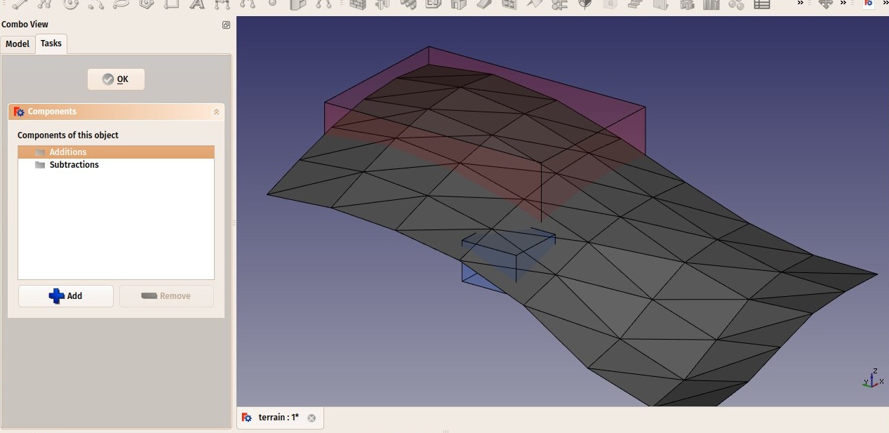
- Możesz dodać objętości do dodania lub odjęcia od podstawowego terenu, dwukrotnie klikając w teren, a następnie dodając obiekty do grup Dodawania lub Odejmowania. Obiekty muszą być bryłami.
- Właściwość DANEwektor wyciągnięcia może być używana do rozwiązania problemów, które mogą pojawić się, gdy teren jest otwartą powłoką, a są dodawane i / lub odejmowane elementy składowe obiektu. Aby wykonać te dodatki / odejmowania, otwarta powłoka jest wyciągana w bryłę, która jest następnie odpowiednio modyfikowana. W zależności od topologii terenu, ta ekstruzja może nie powieść się przy domyślnym wektorze ekstruzji. W takim przypadku można spróbować rozwiązać problem, zmieniając ten wektor na inny. Ta właściwość jest ignorowana, jeśli teren jest bryłą.
Właściwości
Dane
- DANETeren: Podstawowy teren tego obiektu ukształtowania terenu.
- DANEAdres: Ulica i numer domu tego terenu.
- DANEKod pocztowy: Kod pocztowy tego terenu.
- DANEMiasto: Miasto tego terenu.
- DANEKraj: Kraj tego terenu.
- DANESzerokość geograficzna: Szerokość geograficzna tego terenu.
- DANEDługość geograficzna: Długość geograficzna tego terenu.
- DANEURL: Adres URL, który pokazuje ten teren na mapie internetowej.
- DANEPowierzchnia projekcji: Powierzchnia rzutu tego obiektu na płaszczyźnie XY.
- DANEObwód: Długość obwodu tego terenu.
- DANEObjętość dodatkowa: Objętość ziemi do dodania do tego terenu.
- DANEObjętość odejmowania: Objętość ziemi do usunięcia z tego terenu.
- DANEWektor ekstruzji: Wektor wyciągnięcia do użycia podczas operacji logicznych.
- DANEUsuń dzielnik: Usuń dzielniki z wynikowej bryły.
- DANEKąt deklinacji: Kąt między rzeczywistą Północą a kierunkiem Północy w tym dokumencie, czyli osi Y. Oznacza to, że domyślnie Północ wskazuje na oś Y, a Wschód na oś X. Kąt rośnie w kierunku przeciwnym do ruchu wskazówek zegara. Ta właściwość była wcześniej znana jako DANEOdchylenie na północ.
- DANEPlik EPW: Pozwala dołączyć plik EPW z Strony internetowej danych EPW Ladybug do tego terenu. Jest to konieczne do wyświetlania diagramów róż wiatru.
Widok
- WIDOKSolar Diagram: Shows or hides the solar diagram
- WIDOKSolar Diagram Color: The color of the solar diagram
- WIDOKSolar Diagram Position: The position of the solar diagram
- WIDOKSolar Diagram Scale: The scale of the solar diagram
- WIDOKWind Rose: Shows or hides the wind rose diagram (requires the EPW File data property filled, and the Ladybug Python module installed (see below)
Typowy przepływ pracy
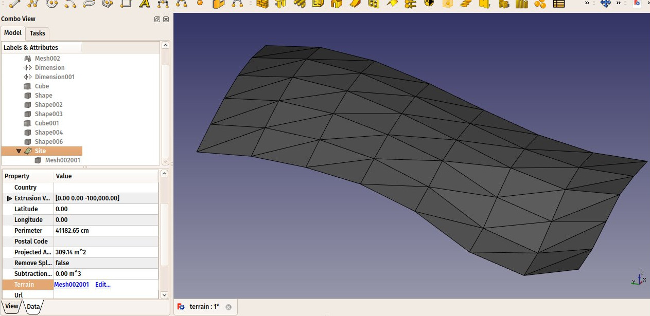
Start by creating an object that represents your terrain. For example, it is easy to import mesh data, that can be turned into a Part Shape from menu Part → Create Shape from Mesh. Then, create a Site object, and set its DANETerrain property to the Part we just created:
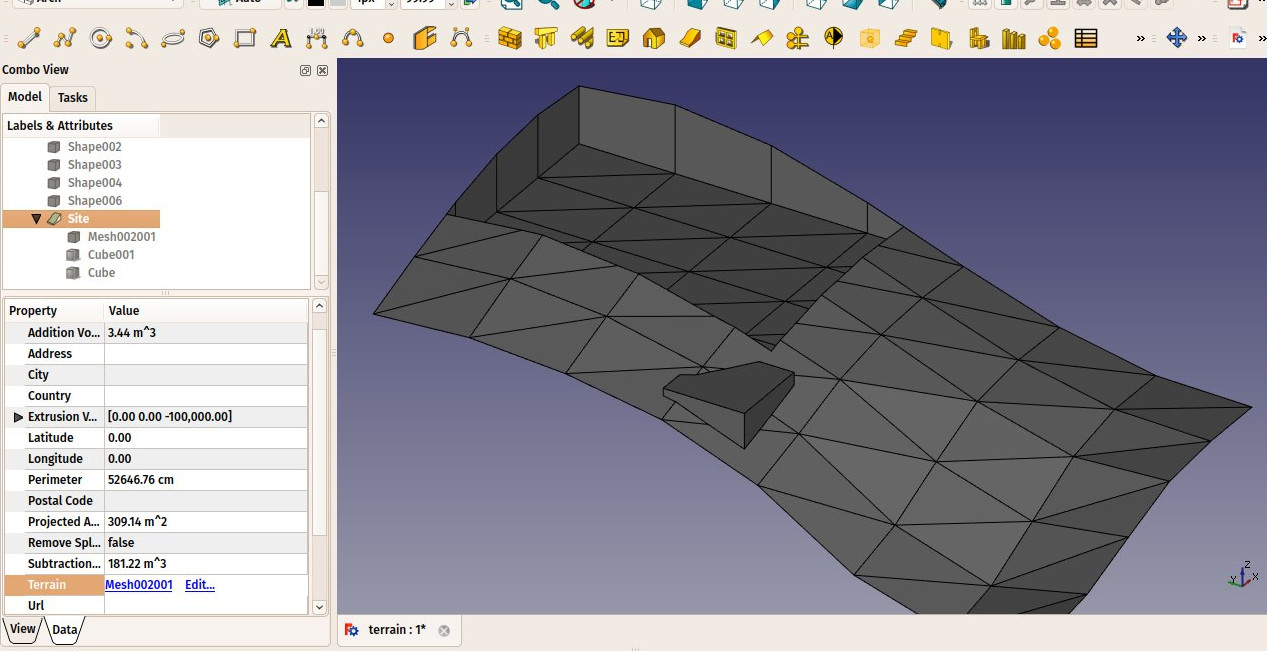
Create some volumes (they must be solids) that represent the areas that you wish to be excavated or filled. Double-click the Site object in the Tree View, and add these volumes to the Additions or Subtractions groups. Click OK.
The site geometry will be recomputed and the areas, perimeter, and volumes properties recalculated.
Wykresy nasłonecznienia i wiatru
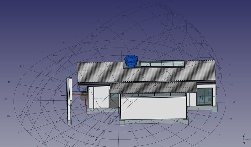
If Ladybug is installed on your system, Arch Sites can display a solar diagram and/or a wind rose. For this, DANELongitude, DANELatitude and DANEDeclination (previously DANENorth Deviation) must be correctly set, and WIDOKSolar Diagram or WIDOKWind Rose set to true.
Note: If you don't have Ladybug, pysolar is still supported to generate solar diagrams, but not wind roses. Pysolar 0.7 or above is required; this version only works with Python 3. If you require this feature with Python 2, you should have Pysolar 0.6 as this is the last version that works with Python 2. However, Ladybug is a much more powerful tool that will probably be used more in the future, so we recommend using it instead of pysolar. Ladybug can be installed simply via pip.
Scripting
See also: Arch API and FreeCAD Scripting Basics.
The Site tool can be used in macros and from the Python console by using the following function:
Site = makeSite(objectslist=None, baseobj=None, name="Site")
- Creates a
Siteobject fromobjectslist, which is a list of objects, orbaseobj, which is aShapeorTerrain.
Example:
import FreeCAD, Draft, Arch

p1 = FreeCAD.Vector(0, 0, 0)
p2 = FreeCAD.Vector(2000, 0, 0)
baseline = Draft.makeLine(p1, p2)
Wall = Arch.makeWall(baseline, length=None, width=150, height=2000)
FreeCAD.ActiveDocument.recompute()

Building = Arch.makeBuilding([Wall])
Site = Arch.makeSite([Building])

FreeCAD.ActiveDocument.recompute()
FreeCAD.Gui.ActiveDocument.ActiveView.viewIsometric()
Solar diagram
As long as the pysolar module is present, a solar diagram can be added to the site. Set the longitude, latitude and declination angles as appropriate, as well as an adequate scale for the size of your model.
Please note that Pysolar 0.7 or above is required, and this version only works with Python 3.
Site.Longitude = -46.38
Site.Latitude = -23.33
Site.Declination = 30
#Site.Compass = True

Site.ViewObject.SolarDiagram = True
Site.ViewObject.SolarDiagramScale = 10000
FreeCAD.ActiveDocument.recompute()
Solar diagram independent of Site
A solar diagram can be created with the following function, independently of any site.
Node = makeSolarDiagram(longitude, latitude, scale=1, complete=False)
- Creates a solar diagram as a Pivy node, using
longitudeandlatitude, with an optionalscale. - If
completeisTrue, the 12 months are drawn, which shows the full solar analemma.
import FreeCADGui, Arch

Node = Arch.makeSolarDiagram(-46.38, -23.33, scale=10000, complete=True)
FreeCAD.Gui.ActiveDocument.ActiveView.getSceneGraph().addChild(Node)
- Elementy: Mury, Konstrukcja, ściana kurtynowa, Okna, Drzwi, Dach, Kubatura, Schody, Wyposażenie, Ramy, Ogrodzenie, Kratownica, Profil, Rura, Kształtka
- Zbrojenie: Pręty zbrojeniowe proste, Pręty zbrojeniowe typu U, Pręty zbrojeniowe typu L, Strzemiona, Strzemiona, Pręty zbrojeniowe spiralne, Zbrojenie słupów, Zbrojenie belek, Zbrojenie płyt stropowych, Zbrojenie stóp fundamentowych, Pręt zbrojeniowy
- Panels: Panel, Panelizacja do cięcia, Arkusz panela, Zagnieżdżanie
- Materiał: Wybór materiału, Materiał złożony
- Organizacja: Część budowli, Projekt, Teren, Budowla, Piętro, Odniesienie, Płaszczyzna przekroju, Obmiar
- Osie: Osie, Układ osi, Siatka
- Modifikacja: Płaszczyzna cięcia, Komponent dodaj, Komponent usuń, Przegląd
- Narzędzia: Komponent, Klonuj komponent, Podziel siatkę, Siatka na kształt, Zaznacz siatki nie bryłowe, Usuń kształt., Zamknij otwory, Połącz ściany, Sprawdź, Przełącz flagę Brep IFC, Trzy widoki, Arkusz kalkulacyjny IFC, Przełącz widoczność odjęcia
- Dodatkowe: Preferencje, Ustawienia Importu i Eksportu (IFC, DAE, OBJ, JSON, 3DS); SHP), Architektura: API
- Jak zacząć
- Instalacja: Pobieranie programu, Windows, Linux, Mac, Dodatkowych komponentów, Docker, AppImage, Ubuntu Snap
- Podstawy: Informacje na temat FreeCAD, Interfejs użytkownika, Profil nawigacji myszką, Metody wyboru, Nazwa obiektu, Edytor ustawień, Środowiska pracy, Struktura dokumentu, Właściwości, Pomóż w rozwoju FreeCAD, Dotacje
- Pomoc: Poradniki, Wideo poradniki
- Środowiska pracy: Strona Startowa, Architektura, Assembly, CAM, Rysunek Roboczy, MES, Inspekcja, Siatka, OpenSCAD, Część, Projekt Części, Punkty, Inżynieria Wsteczna, Robot, Szkicownik, Arkusz Kalkulacyjny, Powierzchnia 3D, Rysunek Techniczny, Test Framework


