TechDraw LengthDimension/pl: Difference between revisions
(Created page with "* '''Kąt linii przedłużenia''': Zastąp wartość kąta linii przedłużenia z osią X widoku ''(w stopniach)''.") |
(Created page with "* '''Użyj wartości domyślnych''': Ustaw kąt linii przedłużającej na zwykły kąt.") |
||
| Line 93: | Line 93: | ||
* '''Kąt linii przedłużenia''': Zastąp wartość kąta linii przedłużenia z osią X widoku ''(w stopniach)''. |
* '''Kąt linii przedłużenia''': Zastąp wartość kąta linii przedłużenia z osią X widoku ''(w stopniach)''. |
||
* '''Użyj wartości domyślnych''': Ustaw kąt linii przedłużającej na zwykły kąt. |
|||
* '''Use default''': Set extension line angle to the usual angle. |
|||
* '''Use selection''': Set extension line angle to match the angle of the selected edge (or 2 vertices) in the view. |
* '''Use selection''': Set extension line angle to match the angle of the selected edge (or 2 vertices) in the view. |
||
Revision as of 14:35, 20 July 2023
|
|
| Lokalizacja w menu |
|---|
| Rysunek Techniczny → Wymiary → Wstaw wymiar długości |
| Środowisko pracy |
| Rysunek Techniczny |
| Domyślny skrót |
| brak |
| Wprowadzono w wersji |
| - |
| Zobacz także |
| Wstaw wymiar poziomy, Wstaw wymiar pionowy |
Opis
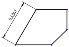
Narzędzie Wstaw wymiar długości dodaje wymiar liniowy do widoku. Wymiar może być odległością między dwoma wierzchołkami, długością jednej krawędzi lub odległością między 2 krawędziami. Wymiar będzie początkowo wyświetlał przewidywaną odległość (tj. jak pokazano na rysunku). Jeśli wymiar jest oparty na odniesieniach 3D, można go zmienić na rzeczywistą odległość 3D, ustawiając właściwość DANETyp pomiaru na Prawda.
Wymiar długości pobrany z dwóch dowolnych węzłów widoku.
Użycie
- Wybierz punkty lub krawędzie, które definiują pomiar. Geometria może być wybrana na rysunku lub w oknie widoku 3D.
- Istnieje kilka sposobów wywołania narzędzia:
- Wymiar zostanie dodany do widoku. Wymiar można przeciągnąć do żądanej pozycji.
- W razie potrzeby dodaj tolerancje zgodnie z opisem na stronie Wymiarowanie geometrii i tolerancja.
Aby zmienić właściwości obiektu wymiaru, kliknij go dwukrotnie na rysunku lub w oknie widoku Drzewa. Spowoduje to otwarcie okna dialogowego wymiaru:
Okno dialogowe
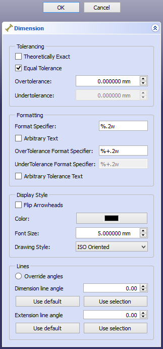
Okno dialogowe wymiaru oferuje następujące ustawienia:

Tolerancja
- W teorii dokładnie: Jeśli to pole jest zaznaczone, wymiar jest określony jako teoretycznie dokładny. W związku z tym nie powinien mieć żadnych tolerancji. Wymiar będzie wyświetlany z ramką wokół wartości:
 .
.
- Tolerancja symetryczna: Jeśli to pole jest zaznaczone, tolerancja nadmierna i tolerancja niedostateczna są równe, a zanegowana wartość tolerancji nadmiernej jest używana jako tolerancja niedostateczna. Wyświetlany będzie symbol
 , w przeciwnym razie będzie to
  .
.
- Powyżej tolerancji:: Wielkość, o jaką wymiar może być większy.
- Poniżej tolerancji:: Wielkość, o jaką wymiar może być mniejszy.
Formatowanie
- Określenie formatu: sposób formatowania wartości wymiaru. Domyślnie specyfikatorem jest
%.xf, gdziexto liczba miejsc dziesiętnych. Składnia formatowania znajduje się na stronie tej strony Wikipedii. Istnieje również dodatkowy format%w, który wyświetla określoną liczbę cyfr po separatorze dziesiętnym i usuwa końcowe zera. Na przykład%.2woznacza, że wypisane zostaną co najwyżej 2 cyfry po przecinku, a końcowe zera zostaną odcięte.
- Dowolny tekst: Jeśli to pole jest zaznaczone, wymiar jest zastępowany zawartością pola "Określenie formatu".
- Określenie formatu górnej granicy tolerancji:: Sposób formatowania wartości powyżej tolerancji. Domyślnie specyfikatorem jest
%.xf, gdziexto liczba miejsc po przecinku. Składnia formatowania znajduje się na stronie tej strony Wikipedii.
- Określenie formatu dolnej granicy tolerancji:: Sposób formatowania wartości Poniżej tolerancji. Domyślnie specyfikatorem jest
%.xf, gdziexto liczba miejsc po przecinku. Składnia formatowania znajduje się na stronie tej strony Wikipedii.
- Dowolne sformułowanie tolerancji: Jeśli opcja ta jest zaznaczona, tolerancje są zastępowane zawartością pól Określenie formatu górnej granicy tolerancji Określenie formatu dolnej granicy tolerancji.
Styl wyświetlania
- Odwróć groty: Odwraca kierunek strzałek linii wymiarowej. Domyślnie znajdują się one wewnątrz linii wymiarowej / łuku i są skierowane na zewnątrz.
- Kolor: Barwa dla linii i tekstu.
- Rozmiar czcionki: Określa rozmiar tekstu.
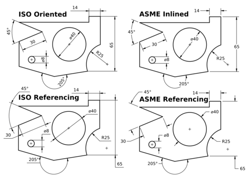
- Styl rysunku: Standard (i jego styl), zgodnie z którym wymiar jest rysowany. Zobacz właściwość Standard i styl, aby uzyskać szczegółowe informacje.
Linia
- Zastąp kąty: Jeśli opcja jest zaznaczona, zwykłe kąty dla linii wymiarowej i linii przedłużenia zostaną zastąpione określonymi wartościami.
- Kąt linii wymiarowej: Zastępuje wartość kąta linii wymiarowej względem osi X widoku (w stopniach).
- Użyj wartości domyślnych: Ustaw kąt linii wymiarowej na zwykły kąt.
- Użyj z wyboru: Ustaw kąt linii wymiarowej tak, aby odpowiadał kątowi wybranej krawędzi (lub 2 wierzchołków) w widoku.
- Kąt linii przedłużenia: Zastąp wartość kąta linii przedłużenia z osią X widoku (w stopniach).
- Użyj wartości domyślnych: Ustaw kąt linii przedłużającej na zwykły kąt.
- Use selection: Set extension line angle to match the angle of the selected edge (or 2 vertices) in the view.
Właściwości
Dane
Podstawowe
- DANEReferences 2D (
LinkSubList): The 2D drawing View object(s) on which the measurement is based. Used if DANEMeasure Type isProjected. - DANEReferences 3D (
LinkSubList): The 3D object(s) on which the measurement is based. Used if DANEMeasure Type isTrue. - DANEType (
Enumeration): Length, radius, diameter, etc. Not normally manipulated by the end user. - DANEMeasure Type (
Enumeration): How the measurement is performed.
True- based on 3D geometry.Projected- based on 2D drawing View geometry.
- DANETheoretical Exact (
Bool): Specifies a theoretically exact (or basic) dimension.
- DANEEqual Tolerance (
Bool): If over- and undertolerance are equal. Then the negated value of the overtolerance is used as undertolerance.
- DANEOver Tolerance (
QuantityConstraint): The amount by which the dimension may be larger. - DANEUnder Tolerance (
QuantityConstraint): The amount by which the dimension may be smaller. - DANEInverted (
Bool): Marks whether the dimension represents a common or an inverted value.
false- the ordinary value is used. For length it is a positive number, for angle the oblique value (0° - 180°).true- the inverted value is used. For length a negative number, for angle the reflex value (180° - 360°).
- DANEX (
Distance): Horizontal position of the dimension text relative to the View. - DANEY (
Distance): Vertical position of the dimension text relative to the View. - DANE (Hidden)Lock Position (
Bool): Locks the position of the dimension text whentrue. - DANE (Hidden)Rotation (
Angle): Read only. - DANE (Hidden)Scale Type (
Enumeration): Read only. - DANE (Hidden)Scale (
FloatConstant): Read only. - DANE (Hidden)Caption (
String): Not used.
Format
- DANEFormat Spec (
String): How the dimension value will be formatted. See Formatting. - DANEFormat Spec Over Tolerance (
String): Like DANEFormat Spec, but for overtolerances. - DANEFormat Spec Under Tolerance (
String): Like DANEFormat Spec, but for undertolerances. - DANEArbitrary (
Bool): Whether the dimension is replaced by the content of the Format Spec field.
false- the content of the Format Spec is used to format the actual dimensional value.true- the content of the Format Spec will be displayed as text instead of the dimension value.
- DANEArbitrary Tolerances (
Bool): Like DANEArbitrary, but for the tolerance.
Override
- DANEAngleOverride (
Bool): Whether the direction of dimension and extension lines is overridden.
false- the directions are computed as usual.true- the directions are overridden by LineAngle and ExtensionAngle property values.
- DANELineAngle (
Angle): angle of dimension line with view X axis (in degrees). - DANEExtensionAngle (
Angle): angle of extension line(s) with view X axis (in degrees).
Widok
Dimension Format
- WIDOKColor (
Color): Color for lines and text. - WIDOKFlip Arrowheads (
Bool): By default the value inside the dimension line/arc means the arrows pointing outwards. If placed outside the dimension line/arc, the arrows point inwards the dimension line/arc.
false- Let the direction of arrows to be selected automatically according to the rule above.true- Override the automatically chosen direction and force the opposite one.
- WIDOKFont (
Font): The name of the font to use for the dimension text. - WIDOKFont Size (
Length): Dimension text size. - WIDOKGap Factor ASME (
Float): Adjusts the gap between the dimension points and the start of the extension lines. The gap is this value times the line width. introduced in version 0.21 - WIDOKGap Factor ISO (
Float): Adjusts the gap between the dimension points and the start of the extension lines. The gap is this value times the line width. introduced in version 0.21 - WIDOKLine Width (
Length): Dimension line weight. - WIDOKRendering Extent (
Enumeration): Rather universal property specifying how much space the dimension drawing may take up:
None- no lines or arrows are drawn, only the bare dimension value is displayed.Minimal- for lengths and angles a single headed line connecting the dimensional value and the end point's virtual extension line is drawn. The extension line itself is not added.- Diameters are rendered following
Confinedextent, radii followingReducedextent. Confined- for lengths and angles a double headed line (or arc) connecting the start and end point's virtual extension lines is drawn, though the extension lines themselves are not added.- Diameters are drawn with a minimal single headed line from dimensional value to the closest point on circle, radii as with
Reducedextent. Reduced- for lengths and angles a single headed line connecting the dimensional value and the end point's extension line is drawn along with the extension line itself.- Diameters are drawn with a single headed line from the center to the closest point on circle, radii with a minimal single headed line from dimensional value to the closest arc point.
Normal- the default value. For lengths and angles a double headed line (or arc) connecting the start and end point's extension lines is drawn, the extension lines themselves as well.- Diameters are drawn as double headed lines striking the center and connecting the closest and farthest points on the circle.
- Radii are drawn as a single headed line from center to the closest arc point.
Expanded- Only diameters support this value, rendering them in a horizontal or vertical length-like way. Other dimension types are rendered as withNormalextent.
- WIDOKStandard And Style (
Enumeration): Specifies the standard (and its style) according to which the dimension is drawn:

ISO Oriented- drawn according to the standard ISO 129-1, text is rotated to be parallel with the dimension line tangent.ISO Referencing- drawn in compliance with ISO 129-1, text is always horizontal, above the shortest possible reference line.ASME Inlined- drawn according to the standard ASME Y14.5M, text is horizontal, inserted in a break within the dimension line or arc.ASME Referencing- drawn in compliance with ASME Y14.5M, text is horizontal, short reference line is attached to one side's vertical center.
Ograniczenia
Dimension objects are vulnerable to the "topological naming problem". This means that if you modify the 3D geometry the faces and edges of the model may be renamed internally; if a dimension is attached to an edge that is then modified, the dimension may break. In general, it is not possible to keep the projected 2D dimensions synchronized with the actual 3D objects.
Therefore, it is recommended that dimensions be added when the 3D model is no longer being modified.
Workaround
If you want to keep a TechDraw view with dimensions that won't break, you need to dimension an object that won't change.
- Select the object that you want to project, then switch to the
Part Workbench and use Part →
Create simple copy. This will create a single object that is not parametric, that is, no longer editable.
- Select this copy, then use TechDraw View, and add the desired dimensions.
- If the original 3D model is modified, the modifications won't affect the simple copy, nor the dimensions in the TechDraw view.
See Landmark Dimensions for another approach to circumventing the topological naming issue.
Tworzenie skryptów
Zobacz również stronę: Dokumentacja API generowana automatycznie oraz Podstawy pisania skryptów dla FreeCAD.
Narzędzie Wymiar długości może być używane w makrodefinicjach i z konsoli Python za pomocą następujących funkcji:
dim1 = FreeCAD.ActiveDocument.addObject('TechDraw::DrawViewDimension','Dimension')
dim1.Type = "Distance"
dim1.References2D=[(view1, 'Edge1')]
rc = page.addView(dim1)
Uwagi
- Edge selection. Edges can be difficult to select. You can adjust the selection area for edges using the parameter "/Mod/TechDraw/General/EdgeFuzz" (see Std_DlgParameter). This is a dimension-less number. The default is 10.0. Values in the 20-30 range will make it noticeably easier to select edges. Large numbers will cause overlaps with other drawing elements.
- Decimal places. Dimensions use the global decimal places setting by default. This can be changed via preferences or by changing the FormatSpec property.
- Multiple objects. Views may contain multiple 3D objects as Source. Dimensions may be applied to geometry from any object(s) in the View (ex from Object1.Vertex0 to Object2.Vertex3).
- Strona rysunku: Wstaw nową domyślna stronę rysunku, Szablon strony, Przerysuj stronę, Drukuj wszystkie strony
- Widok: Wstaw widok, Aktywny widok, Grupa rzutów, Widok przekroju, Przekrój złożony, Widok szczegółu, Wstaw widok obiektu środowiska Kreślenie, Wstaw widok obiektu środowiska Architektura, Wstaw widok arkusza kalkulacyjnego, Wstaw grupę wycinków, Udostępnij widok, Rzut kształtu
- Wymiarowanie: Wymiar długości, Wstaw wymiar poziomy, Wstaw wymiar pionowy, Wymiaruj promień, Wymiar średnicy, Wymiaruj kąt, Wymiaruj kąt na podstawie trzech punktów, Wymiar poziomy, Wymiar pionowy, Powiązanie wymiaru, Dymek, Wymiar długości w aksonometrii, Wymiar przestrzenny, Napraw wymiar
- Dekoracje: Zakreskuj, Kreskowanie geometryczne, Symbol, Obraz, Włącz / wyłącz wyświetlanie ramek
- Adnotacje: Nowa adnotacja, Linia odniesienia, Adnotacja w postaci tekstu sformatowanego, Geometria pomocnicza - wierzchołek, Punkt środkowy, Kwadrant, Dodaj linię środkową do ściany, Dodaj linię środkową pomiędzy dwoma liniami, Dodaj linię środkową pomiędzy dwoma punktami , Dodaj linię pomocniczą wytyczoną przez dwa punkty, Dodaj okrąg kosmetyczny, Zmień wygląd linii, Wyświetl / ukryj niewidoczne krawędzie, Symbol spawalniczy, Symbol wykończenia powierzchnii, Pasowanie wału / otworu
- Rozszerzenia:
- Atrybuty i modyfikacje: Wybierz Atrybuty linii, odstępy między kaskadami, Zmień atrybuty linii, Przedłużenie linii, Skróć linie, Zablokuj / odblokuj widok, Wyrównaj widok przekroju, Wyrównaj ciąg wymiarów poziomych, Wyrównaj ciąg wymiarów pionowych, Wyrównaj ciąg wymiarów ukośnych, Wymiar poziomy kaskadowo, Wymiar pionowy kaskadowo, Wymiar ukośny kaskadowo, Opis - pole powierzchni, Oblicz długość łuku dla zaznaczonych krawędzi, Rozszerzenie dostosuj format
- Linie środkowe i gwinty: Oś otworu, Rozszerzenie Osie otworów w okręgu, AGeometria pomocnicza dla otworu gwintowanego, widok z boku, Geometria pomocnicza dla otworu gwintowanego, widok od dołu, Geometria pomocnicza dla gwintu śruby, widok z boku, Geometria pomocnicza dla śruby, widok od dołu, Utwórz wierzchołki w przecięciu, Geometria pomocnicza obwodu, Geometria pomocnicza łuku, Geometria pomocnicza okręgu przez trzy punkty, Rozszerzenie Linia równoległa, Rozszerzenie Linia prostopadła
- Wymiarowanie: Seria wymiarów poziomych, Seria wymiarów pionowych, Seria wymiarów ukośnie, Seria kaskadowych wymiarów poziomo, Seria kaskadowych wymiarów pionowo, Seria kaskadowych wymiarów ukośnie, Wymiar poziomy fazki, Wymiar pionowy fazki, Długość łuku, Symbol średnicy '⌀', Symbol kwadratu '〼', Usuń symbol wiodący, Zwiększenie dokładności, Zmniejszenie dokładności
- Jak zacząć
- Instalacja: Pobieranie programu, Windows, Linux, Mac, Dodatkowych komponentów, Docker, AppImage, Ubuntu Snap
- Podstawy: Informacje na temat FreeCAD, Interfejs użytkownika, Profil nawigacji myszką, Metody wyboru, Nazwa obiektu, Edytor ustawień, Środowiska pracy, Struktura dokumentu, Właściwości, Pomóż w rozwoju FreeCAD, Dotacje
- Pomoc: Poradniki, Wideo poradniki
- Środowiska pracy: Strona Startowa, Architektura, Assembly, CAM, Rysunek Roboczy, MES, Inspekcja, Siatka, OpenSCAD, Część, Projekt Części, Punkty, Inżynieria Wsteczna, Robot, Szkicownik, Arkusz Kalkulacyjny, Powierzchnia 3D, Rysunek Techniczny, Test Framework
