Measurement Of Angles On Holes/pl: Difference between revisions
(Created page with "==Sposób postępowania==") |
(Created page with "1. Ustawianie linii środkowych na otworach:") |
||
| Line 17: | Line 17: | ||
==Sposób postępowania== |
==Sposób postępowania== |
||
1. Ustawianie linii środkowych na otworach: |
|||
1. Setting center lines on holes: |
|||
There are some possibilities to create a center line for holes. |
There are some possibilities to create a center line for holes. |
||
Revision as of 15:52, 7 August 2020
| Temat |
|---|
| TechDraw |
| Poziom trudności |
| Podstawowy |
| Czas wykonania |
| 1 minuta |
| Autorzy |
| AnHi |
| Wersja FreeCAD |
| 0.19 |
| Pliki z przykładami |
| Nie dołączono |
| Zobacz również |
| - |
Wprowadzenie
Ten poradnik wyjaśnia, jak tworzyć środkowe linie otworów przy pomocy Środowiska pracy Tech Draw z dokładnie ustawionymi otworami.
Tworząc kąty dla otworów, nie jest możliwe użycie pionowych lub poziomych linii środkowych (fałsz / prawda) z właściwości widoku. W związku z tą koniecznością tworzone są linie pomocnicze i / lub punkty pomocnicze.
Sposób postępowania
1. Ustawianie linii środkowych na otworach:
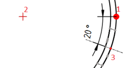
There are some possibilities to create a center line for holes. At first the lines or points on the hole must be selected as shown below. Second, the following tools can be used from the toolbar to create the center line:
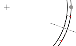
Above: created with which creates centerlines between 2 points
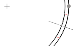
Above: created with which creates centerlines between 2 lines
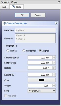
In the dialog box choice "Aligned" for axes out of main axes. "Extend by" means the length of the center line beyond of the body line in the drawing. With "Shift Horiz." and "Shift Vert." the center line can move in horizontal or vertical direction, if is necessary. "Stil" means the figure of center line.

Above: dialog box
The created center line can change. Select the center line and press the button or
from the tool bar which you have created the center line. Delete the center line only with
from the tool bar after selecting the center line.
2. Setting angles:
Quadrant points select with from the tool bar. Next select the points as show below and use
from the tool bar to create the angle. Other succession create other angles.
Is there no catching point on the center line change "ISO count" in the properties.

Above: Succession of selection
- Strona rysunku: Wstaw nową domyślna stronę rysunku, Szablon strony, Przerysuj stronę, Drukuj wszystkie strony
- Widok: Wstaw widok, Aktywny widok, Grupa rzutów, Widok przekroju, Przekrój złożony, Widok szczegółu, Wstaw widok obiektu środowiska Kreślenie, Wstaw widok obiektu środowiska Architektura, Wstaw widok arkusza kalkulacyjnego, Wstaw grupę wycinków, Udostępnij widok, Rzut kształtu
- Wymiarowanie: Wymiar długości, Wstaw wymiar poziomy, Wstaw wymiar pionowy, Wymiaruj promień, Wymiar średnicy, Wymiaruj kąt, Wymiaruj kąt na podstawie trzech punktów, Wymiar poziomy, Wymiar pionowy, Powiązanie wymiaru, Dymek, Wymiar długości w aksonometrii, Wymiar przestrzenny, Napraw wymiar
- Dekoracje: Zakreskuj, Kreskowanie geometryczne, Symbol, Obraz, Włącz / wyłącz wyświetlanie ramek
- Adnotacje: Nowa adnotacja, Linia odniesienia, Adnotacja w postaci tekstu sformatowanego, Geometria pomocnicza - wierzchołek, Punkt środkowy, Kwadrant, Dodaj linię środkową do ściany, Dodaj linię środkową pomiędzy dwoma liniami, Dodaj linię środkową pomiędzy dwoma punktami , Dodaj linię pomocniczą wytyczoną przez dwa punkty, Dodaj okrąg kosmetyczny, Zmień wygląd linii, Wyświetl / ukryj niewidoczne krawędzie, Symbol spawalniczy, Symbol wykończenia powierzchnii, Pasowanie wału / otworu
- Rozszerzenia:
- Atrybuty i modyfikacje: Wybierz Atrybuty linii, odstępy między kaskadami, Zmień atrybuty linii, Przedłużenie linii, Skróć linie, Zablokuj / odblokuj widok, Wyrównaj widok przekroju, Wyrównaj ciąg wymiarów poziomych, Wyrównaj ciąg wymiarów pionowych, Wyrównaj ciąg wymiarów ukośnych, Wymiar poziomy kaskadowo, Wymiar pionowy kaskadowo, Wymiar ukośny kaskadowo, Opis - pole powierzchni, Oblicz długość łuku dla zaznaczonych krawędzi, Rozszerzenie dostosuj format
- Linie środkowe i gwinty: Oś otworu, Rozszerzenie Osie otworów w okręgu, AGeometria pomocnicza dla otworu gwintowanego, widok z boku, Geometria pomocnicza dla otworu gwintowanego, widok od dołu, Geometria pomocnicza dla gwintu śruby, widok z boku, Geometria pomocnicza dla śruby, widok od dołu, Utwórz wierzchołki w przecięciu, Geometria pomocnicza obwodu, Geometria pomocnicza łuku, Geometria pomocnicza okręgu przez trzy punkty, Rozszerzenie Linia równoległa, Rozszerzenie Linia prostopadła
- Wymiarowanie: Seria wymiarów poziomych, Seria wymiarów pionowych, Seria wymiarów ukośnie, Seria kaskadowych wymiarów poziomo, Seria kaskadowych wymiarów pionowo, Seria kaskadowych wymiarów ukośnie, Wymiar poziomy fazki, Wymiar pionowy fazki, Długość łuku, Symbol średnicy '⌀', Symbol kwadratu '〼', Usuń symbol wiodący, Zwiększenie dokładności, Zmniejszenie dokładności
- Jak zacząć
- Instalacja: Pobieranie programu, Windows, Linux, Mac, Dodatkowych komponentów, Docker, AppImage, Ubuntu Snap
- Podstawy: Informacje na temat FreeCAD, Interfejs użytkownika, Profil nawigacji myszką, Metody wyboru, Nazwa obiektu, Edytor ustawień, Środowiska pracy, Struktura dokumentu, Właściwości, Pomóż w rozwoju FreeCAD, Dotacje
- Pomoc: Poradniki, Wideo poradniki
- Środowiska pracy: Strona Startowa, Architektura, Assembly, CAM, Rysunek Roboczy, MES, Inspekcja, Siatka, OpenSCAD, Część, Projekt Części, Punkty, Inżynieria Wsteczna, Robot, Szkicownik, Arkusz Kalkulacyjny, Powierzchnia 3D, Rysunek Techniczny, Test Framework

