Poradnik: Rysunek Techniczny, Koło Podziałowe
| Temat |
|---|
| Rysunek Techniczny |
| Poziom trudności |
| Początkujący |
| Czas wykonania |
| 10 minut |
| Autorzy |
| Andergrin |
| Wersja FreeCAD |
| 0.19 |
| Pliki z przykładami |
| Nie dołączono |
| Zobacz również |
| - |
Wprowadzenie
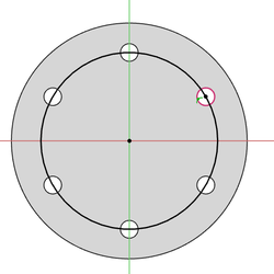
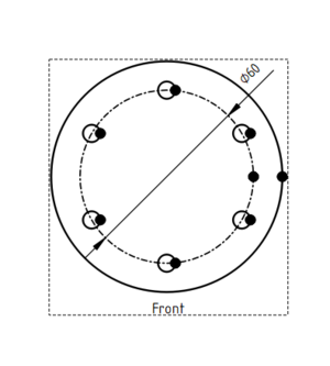
Ten poradnik wyjaśnia jak dodać okrąg podziałowy do widoku Rysunku Technicznego. Zakłada on, że model jest obiektem środowiska
Projekt Części z co najmniej trzema otworami w układzie kołowym. Dla okręgu zostanie utworzony osobny szkic. Podobna procedura może być użyta w innych sytuacjach oraz do dodawania innych elementów podobnych do adnotacji na widoku Rysunku Technicznego.
Tworzenie szkicu okręgu
- Activate the
PartDesign Body.
- If required: switch to the
PartDesign Workbench.
- In the 3D view select the correct face belonging to the body.
- Create a new sketch with the
PartDesign NewSketch command.
- The sketch will be attached to the selected face.
- Call the
Sketcher External command.
- Select three circular edges (holes) from the body.
- Use the
Sketcher Create3PointCircle command to create a circle constrained to the center points of the external geometry.
- The sketch should now be fully constrained.
- Close the sketch.
Tworzenie widoku Rysunku Technicznego
- Switch to the
TechDraw Workbench.
- If you don't have one already: create a
TechDraw page.
- Make sure the 3D view is properly aligned.
- Hold down the Ctrl key and in the Tree view select the body and the sketch that was just just created.
- Insert a new view by calling the
TechDraw View command.
- Switch to the TechDraw page.
- Select the circle.
- Call the
TechDraw DecorateLine command.
- Change the Style and Weight of the circle.
- Strona rysunku: Wstaw nową domyślna stronę rysunku, Szablon strony, Przerysuj stronę, Drukuj wszystkie strony
- Widok: Wstaw widok, Aktywny widok, Grupa rzutów, Widok przekroju, Przekrój złożony, Widok szczegółu, Wstaw widok obiektu środowiska Kreślenie, Wstaw widok obiektu środowiska Architektura, Wstaw widok arkusza kalkulacyjnego, Wstaw grupę wycinków, Udostępnij widok, Rzut kształtu
- Wymiarowanie: Wymiar długości, Wstaw wymiar poziomy, Wstaw wymiar pionowy, Wymiaruj promień, Wymiar średnicy, Wymiaruj kąt, Wymiaruj kąt na podstawie trzech punktów, Wymiar poziomy, Wymiar pionowy, Powiązanie wymiaru, Dymek, Wymiar długości w aksonometrii, Wymiar przestrzenny, Napraw wymiar
- Dekoracje: Zakreskuj, Kreskowanie geometryczne, Symbol, Obraz, Włącz / wyłącz wyświetlanie ramek
- Adnotacje: Nowa adnotacja, Linia odniesienia, Adnotacja w postaci tekstu sformatowanego, Geometria pomocnicza - wierzchołek, Punkt środkowy, Kwadrant, Dodaj linię środkową do ściany, Dodaj linię środkową pomiędzy dwoma liniami, Dodaj linię środkową pomiędzy dwoma punktami , Dodaj linię pomocniczą wytyczoną przez dwa punkty, Dodaj okrąg kosmetyczny, Zmień wygląd linii, Wyświetl / ukryj niewidoczne krawędzie, Symbol spawalniczy, Symbol wykończenia powierzchnii, Pasowanie wału / otworu
- Rozszerzenia:
- Atrybuty i modyfikacje: Wybierz Atrybuty linii, odstępy między kaskadami, Zmień atrybuty linii, Przedłużenie linii, Skróć linie, Zablokuj / odblokuj widok, Wyrównaj widok przekroju, Wyrównaj ciąg wymiarów poziomych, Wyrównaj ciąg wymiarów pionowych, Wyrównaj ciąg wymiarów ukośnych, Wymiar poziomy kaskadowo, Wymiar pionowy kaskadowo, Wymiar ukośny kaskadowo, Opis - pole powierzchni, Oblicz długość łuku dla zaznaczonych krawędzi, Rozszerzenie dostosuj format
- Linie środkowe i gwinty: Oś otworu, Rozszerzenie Osie otworów w okręgu, AGeometria pomocnicza dla otworu gwintowanego, widok z boku, Geometria pomocnicza dla otworu gwintowanego, widok od dołu, Geometria pomocnicza dla gwintu śruby, widok z boku, Geometria pomocnicza dla śruby, widok od dołu, Utwórz wierzchołki w przecięciu, Geometria pomocnicza obwodu, Geometria pomocnicza łuku, Geometria pomocnicza okręgu przez trzy punkty, Rozszerzenie Linia równoległa, Rozszerzenie Linia prostopadła
- Wymiarowanie: Seria wymiarów poziomych, Seria wymiarów pionowych, Seria wymiarów ukośnie, Seria kaskadowych wymiarów poziomo, Seria kaskadowych wymiarów pionowo, Seria kaskadowych wymiarów ukośnie, Wymiar poziomy fazki, Wymiar pionowy fazki, Długość łuku, Symbol średnicy '⌀', Symbol kwadratu '〼', Usuń symbol wiodący, Zwiększenie dokładności, Zmniejszenie dokładności
- Jak zacząć
- Instalacja: Pobieranie programu, Windows, Linux, Mac, Dodatkowych komponentów, Docker, AppImage, Ubuntu Snap
- Podstawy: Informacje na temat FreeCAD, Interfejs użytkownika, Profil nawigacji myszką, Metody wyboru, Nazwa obiektu, Edytor ustawień, Środowiska pracy, Struktura dokumentu, Właściwości, Pomóż w rozwoju FreeCAD, Dotacje
- Pomoc: Poradniki, Wideo poradniki
- Środowiska pracy: Strona Startowa, Architektura, Assembly, CAM, Rysunek Roboczy, MES, Inspekcja, Siatka, OpenSCAD, Część, Projekt Części, Punkty, Inżynieria Wsteczna, Robot, Szkicownik, Arkusz Kalkulacyjny, Powierzchnia 3D, Rysunek Techniczny, Test Framework

