TechDraw ArchView/pl: Difference between revisions
(Created page with "Widok architektoniczny jest renderowany w środowisku Architektura, dlatego środowisko Rysunek Techniczny ma ograniczoną kontrolę nad jego wyglądem. Może być konieczne wprowadzenie zmian w środowisku pierwotnym, aby uzyskać pożądaną reprezentację.") |
(Created page with "==Opcje==") |
||
| Line 38: | Line 38: | ||
Widok architektoniczny jest renderowany w środowisku [[Arch_Workbench/pl|Architektura]], dlatego środowisko Rysunek Techniczny ma ograniczoną kontrolę nad jego wyglądem. Może być konieczne wprowadzenie zmian w środowisku pierwotnym, aby uzyskać pożądaną reprezentację. |
Widok architektoniczny jest renderowany w środowisku [[Arch_Workbench/pl|Architektura]], dlatego środowisko Rysunek Techniczny ma ograniczoną kontrolę nad jego wyglądem. Może być konieczne wprowadzenie zmian w środowisku pierwotnym, aby uzyskać pożądaną reprezentację. |
||
= |
<span id="Options"></span> |
||
==Opcje== |
|||
* The Arch View is rendered by the [[Arch_Workbench|Arch Workbench]]. |
* The Arch View is rendered by the [[Arch_Workbench|Arch Workbench]]. |
||
Revision as of 16:14, 19 July 2023
|
|
| Lokalizacja w menu |
|---|
| Rysunek Techniczny → Insert Arch Workbench Object |
| Środowisko pracy |
| Rysunek Techniczny, Architektura |
| Domyślny skrót |
| brak |
| Wprowadzono w wersji |
| - |
| Zobacz także |
| Płaszczyzna przekroju |
Opis
Narzędzie Wstaw obiekt środowiska Architektura wstawia widok przekroju na stronie Rysunku Technicznego.
Użycie
- Wybierz płaszczyznę przekroju architektonicznego w oknie widoku 3D lub w widoku drzewa.
- Jeśli w dokumencie znajduje się wiele stron rysunku, należy wybrać żądaną stronę w drzewie.
- Naciśnij
Wstaw obiekt środowiska Architektura.
- Na stronie pojawi się widok obiektów widzianych przez płaszczyznę przekroju.
Ograniczenia
Widok architektoniczny jest renderowany w środowisku Architektura, dlatego środowisko Rysunek Techniczny ma ograniczoną kontrolę nad jego wyglądem. Może być konieczne wprowadzenie zmian w środowisku pierwotnym, aby uzyskać pożądaną reprezentację.
Opcje
- The Arch View is rendered by the Arch Workbench.
- Draft Dimensions, Draft Texts and any other 2D (Sketch or Draft) object considered by the section plane is rendered "as is" (no intersection or hidden lines) on top of the solid geometry
- The volume of Arch Spaces is not rendered, only the label will be rendered
- Cut lines, projected lines (if Show Hidden property is set to True) and 2D lines above can be rendered with different line widths. This can be configured in the Arch preferences.
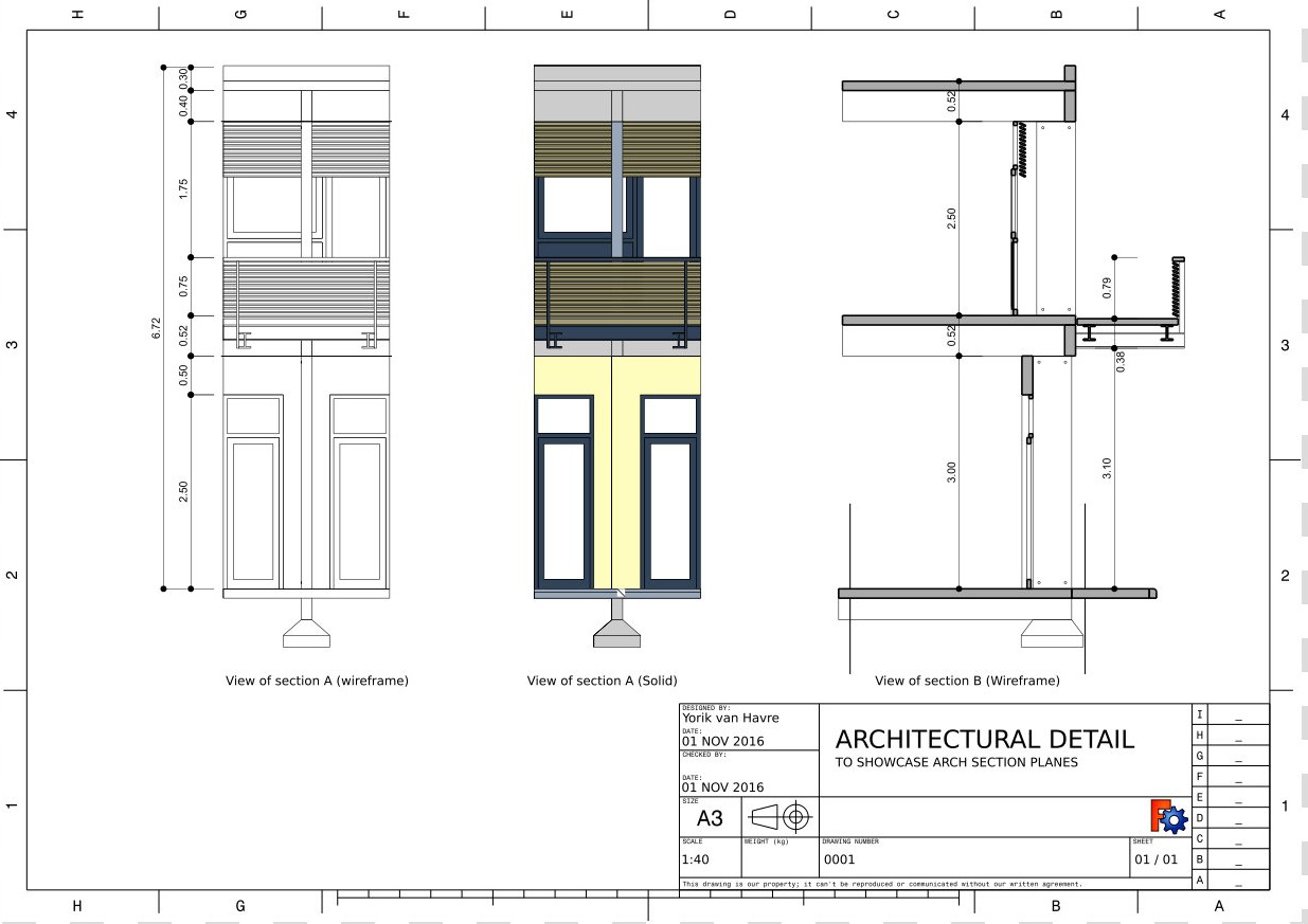
- The ArchView has two rendering modes:
- Wireframe, which uses the OpenCasCade algorithms of the TechDraw Workbench, is fast and produces only lines (no face fill possible)
- Solid, which is based on the Painter's algorithm, and is capable of rendering faces filled with their shape color. However, it is much slower and can fail in many situations.
- The image below illustrates the difference between the two rendering modes:
- Only the base line of Arch Pipes is rendered, not the full volume of the tube:
Properties
See also TechDraw View.
Data
Arch view
- DANESource (
Link): The section plane object to be displayed. - DANEAll On (
Bool): If hidden objects must be shown or not. Iffalse, only objects that are visible in the 3D view are rendered. - DANERender Mode (
Enumeration): The render mode to use,SolidorWireframe. - DANEFill Spaces (
Bool): Iftrue, Arch Spaces are shown as a colored area. - DANEShow Hidden (
Bool): If the hidden geometry (the part of the geometry that lies behind the section plane) is shown or not. It will be rendered in dashed line, which can be configured in the Arch preferences. - DANEShow Fill (
Bool): If cut areas must be filled with a grey color or not. - DANELine Width (
Float): The width of the main lines. Cut lines and projected/2D line widths ratios can be configured in the Arch preferences. - DANEFont Size (
Float): The size of all texts that appear in this view. - DANECut Line Width (
Float): Width of the cut lines in this view. - DANEJoin Arch (
Bool): Iftrue, walls and structures will be fused by material.
Scripting
See also: Autogenerated API documentation and FreeCAD Scripting Basics.
The ArchView tool can be used in macros and from the Python console by using the following functions:
dv = FreeCAD.ActiveDocument.addObject('TechDraw::DrawViewArch','TestArch')
dv.Source = mySectionPlane
rc = page.addView(dv)
- Strona rysunku: Wstaw nową domyślna stronę rysunku, Szablon strony, Przerysuj stronę, Drukuj wszystkie strony
- Widok: Wstaw widok, Aktywny widok, Grupa rzutów, Widok przekroju, Przekrój złożony, Widok szczegółu, Wstaw widok obiektu środowiska Kreślenie, Wstaw widok obiektu środowiska Architektura, Wstaw widok arkusza kalkulacyjnego, Wstaw grupę wycinków, Udostępnij widok, Rzut kształtu
- Wymiarowanie: Wymiar długości, Wstaw wymiar poziomy, Wstaw wymiar pionowy, Wymiaruj promień, Wymiar średnicy, Wymiaruj kąt, Wymiaruj kąt na podstawie trzech punktów, Wymiar poziomy, Wymiar pionowy, Powiązanie wymiaru, Dymek, Wymiar długości w aksonometrii, Wymiar przestrzenny, Napraw wymiar
- Dekoracje: Zakreskuj, Kreskowanie geometryczne, Symbol, Obraz, Włącz / wyłącz wyświetlanie ramek
- Adnotacje: Nowa adnotacja, Linia odniesienia, Adnotacja w postaci tekstu sformatowanego, Geometria pomocnicza - wierzchołek, Punkt środkowy, Kwadrant, Dodaj linię środkową do ściany, Dodaj linię środkową pomiędzy dwoma liniami, Dodaj linię środkową pomiędzy dwoma punktami , Dodaj linię pomocniczą wytyczoną przez dwa punkty, Dodaj okrąg kosmetyczny, Zmień wygląd linii, Wyświetl / ukryj niewidoczne krawędzie, Symbol spawalniczy, Symbol wykończenia powierzchnii, Pasowanie wału / otworu
- Rozszerzenia:
- Atrybuty i modyfikacje: Wybierz Atrybuty linii, odstępy między kaskadami, Zmień atrybuty linii, Przedłużenie linii, Skróć linie, Zablokuj / odblokuj widok, Wyrównaj widok przekroju, Wyrównaj ciąg wymiarów poziomych, Wyrównaj ciąg wymiarów pionowych, Wyrównaj ciąg wymiarów ukośnych, Wymiar poziomy kaskadowo, Wymiar pionowy kaskadowo, Wymiar ukośny kaskadowo, Opis - pole powierzchni, Oblicz długość łuku dla zaznaczonych krawędzi, Rozszerzenie dostosuj format
- Linie środkowe i gwinty: Oś otworu, Rozszerzenie Osie otworów w okręgu, AGeometria pomocnicza dla otworu gwintowanego, widok z boku, Geometria pomocnicza dla otworu gwintowanego, widok od dołu, Geometria pomocnicza dla gwintu śruby, widok z boku, Geometria pomocnicza dla śruby, widok od dołu, Utwórz wierzchołki w przecięciu, Geometria pomocnicza obwodu, Geometria pomocnicza łuku, Geometria pomocnicza okręgu przez trzy punkty, Rozszerzenie Linia równoległa, Rozszerzenie Linia prostopadła
- Wymiarowanie: Seria wymiarów poziomych, Seria wymiarów pionowych, Seria wymiarów ukośnie, Seria kaskadowych wymiarów poziomo, Seria kaskadowych wymiarów pionowo, Seria kaskadowych wymiarów ukośnie, Wymiar poziomy fazki, Wymiar pionowy fazki, Długość łuku, Symbol średnicy '⌀', Symbol kwadratu '〼', Usuń symbol wiodący, Zwiększenie dokładności, Zmniejszenie dokładności
- Jak zacząć
- Instalacja: Pobieranie programu, Windows, Linux, Mac, Dodatkowych komponentów, Docker, AppImage, Ubuntu Snap
- Podstawy: Informacje na temat FreeCAD, Interfejs użytkownika, Profil nawigacji myszką, Metody wyboru, Nazwa obiektu, Edytor ustawień, Środowiska pracy, Struktura dokumentu, Właściwości, Pomóż w rozwoju FreeCAD, Dotacje
- Pomoc: Poradniki, Wideo poradniki
- Środowiska pracy: Strona Startowa, Architektura, Assembly, CAM, Rysunek Roboczy, MES, Inspekcja, Siatka, OpenSCAD, Część, Projekt Części, Punkty, Inżynieria Wsteczna, Robot, Szkicownik, Arkusz Kalkulacyjny, Powierzchnia 3D, Rysunek Techniczny, Test Framework


