Środowisko pracy Złożenie

Wprowadzenie
Środowisko pracy Złożenie to nowe wbudowane środowisko pracy FreeCAD.
Narzędzia
Funkcje eksperymentalne nie są domyślnie dostępne. Aby je włączyć, zapoznaj się z informacjami na stronie Dostrajanie parametrów.
Złożenie
Połączenia
Przykład
 Ten przykład jest tymczasowy i może zostać usunięty, gdy dostępne będą odpowiednie opisy / poradniki.
Złożenie kinematyczne
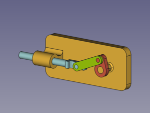
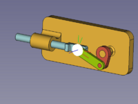
Zespół kinematyczny, który ma zostać utworzony, składa się z czterech części: podstawy, suwaka, korby i pręta łączącego. Są one połączone czterema przegubami.
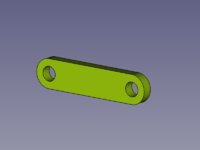
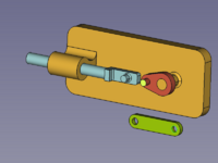
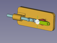
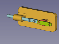
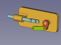
Złożone części: Podstawa (bursztynowy), Suwak (jasnoniebieski), Korba (czerwony), Korbowód (zielony)
Przygotowanie części
W tym przykładzie wszystkie części i zespół są tworzone w jednym dokumencie.
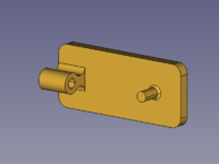
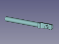
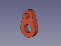
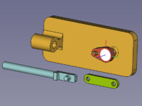
Od lewej do prawej: Podstawa, suwak, korba, korbowód.
Geometrie cylindryczne są równoległe lub prostopadłe, pozostałe kształty nie są istotne dla tego przykładu, chyba że powodują kolizje. Mając to na uwadze, wymodeluj własne kształty.
Dodawanie złożenia głównego
Utwórz złożenie dodaje do dokumentu złożenie główne. (narzędzie to może również dodać podzespół do istniejącego wybranego złożenia)
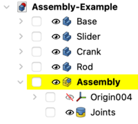
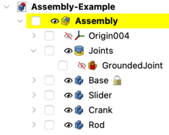
Widok drzewa części i złożeń w dokumencie.
Przenieś części do kontenera złożożeń
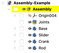
W Widoku drzewa przeciągnij i upuść części na obiekt Złożenia. Teraz mogą być one obsługiwane przez solver złożeń.
Części są teraz w kontenerze złożeń.
Kotwienie części
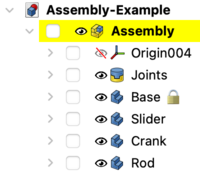
To keep the assembly at the desired position, the base part should be locked, or grounded as it is called here. Select the Base in the Tree view or in the 3D view and use the Toggle grounded command. This fixes the position of the Base in relation to the local coordinate system (LCS) of the Assembly container. This (also suffixes a lock icon to the label of the Base object and (before weekly build 0.22 - 37213)) adds a GroundedJoint object in the Joints container.
Rozwiń kontener Połączeń, aby znaleźć obiekt Zakotwienia połaczeń.
(Obiekt Zakotwienia połączeń nie może zostać usunięty i nie ma reprezentacji w widoku 3D (przed cotygodniową kompilacją 0.22 - 37213)).
Apply joints
A joint connects exactly two elements of different parts. They can optionally be selected before the desired joint tool is invoked (any number of selected elements other than two results in an empty selection).
The elements define the position and orientation of a LCS represented by a filled circle on the local XY plane and three lines along the local X (red), Y (green), and Z (blue) axes.
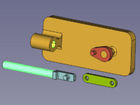
- A Revolute joint between Base and Crank
Selected elements + Create Revolute Joint → rearranged Crank
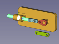
- A Cylindrical joint between Base and Slider
Selected elements + Create Cylindrical Joint → rearranged Slider
- A Revolute joint between Crank and Rod
Selected elements + Create Revolute Joint → rearranged Rod
Now there are several joints in a line and we have to help the solver to find a sensible solution.
Click and drag the parts → into an easier to compute position.
- A Cylindrical joint between Rod and Slider
Selected elements + Create Cylindrical Joint → finished Assembly
In the finished assembly use the mouse pointer to drag the parts according to the used joints.
Drive the crank
To control the layout of the assembly by the angle between the Base and the Crank we have to change the Revolute joint to a Fixed joint.
To do so double-click on the Revolute object in the Tree view. In the dialog change Revolute to Fixed and change the Rotation value as desired (the movement should follow the mouse wheel action).
Now only the Label of the joint was changed but not its Name! (Each change of the joint type will also change the Label)
The Rotation property of the Fixed joint can be controlled via macro or from the python console (just copy and paste the following lines):
actuator = FreeCAD.ActiveDocument.getObject('Revolute')

for angle in range(0,361,10):
    # A full rotation of the Crank in steps of 10°
    actuator.Rotation = angle
    App.activeDocument().recompute(None,True,True)
Or alternatively:
actuator = FreeCAD.ActiveDocument.getObject('Revolute')

for angle in range(0,361,10):
    # A full rotation of the Crank in steps of 10°
    actuator.Rotation = angle
    Gui.runCommand('Assembly_SolveAssembly',0)
(The Name of the joint is still Revolute while its Label has changed to Fixed, and the end of the range must be greater than 360 to also include this angle as a valid result.)
- Złożenie: Utwórz złożenie, Wstaw łącze, Rozwiąż złożenie, Utwórz widok rozłożenia, Eksportuj do pliku ASMT
- Połaczenia: Włącz / wyłącz zakotwienie, Utwórz połączenie stałe, Utwórz połączenie obrotowe, Utwórz połączenie cylindryczne, Utwórz połączenie przesuwne, Utwórz przegub kulowy, Utwórz połączenie dystansowe, Utwórz połączenie zębatki i koła zębatego, Utwórz połączenie śrubowe, Utwórz połączenie kół zębatych, Utwórz połączenie pasowe
- Jak zacząć
- Instalacja: Pobieranie programu, Windows, Linux, Mac, Dodatkowych komponentów, Docker, AppImage, Ubuntu Snap
- Podstawy: Informacje na temat FreeCAD, Interfejs użytkownika, Profil nawigacji myszką, Metody wyboru, Nazwa obiektu, Edytor ustawień, Środowiska pracy, Struktura dokumentu, Właściwości, Pomóż w rozwoju FreeCAD, Dotacje
- Pomoc: Poradniki, Wideo poradniki
- Środowiska pracy: Strona Startowa, Złożenie, BIM, CAM, Rysunek Roboczy, MES, Inspekcja, Siatka, OpenSCAD, Część, Projekt Części, Punkty, Inżynieria Wsteczna, Robot, Szkicownik, Arkusz Kalkulacyjny, Powierzchnia 3D, Rysunek Techniczny, Test Framework


