Edytor ustawień
Ustawienia FreeCAD znajdują się w Menu Edycja → Preferencje.
Funkcjonalność FreeCAD jest podzielona na różne moduły, z których każdy jest odpowiedzialny za działanie konkretnego Środowiska pracy. FreeCAD wykorzystuje również koncepcję zwaną late loading, co oznacza, że komponenty są ładowane tylko wtedy, gdy są potrzebne. Być może zauważyłeś, że gdy zmienisz Środowisko pracy na pasku narzędzi FreeCAD, to wszystkie jego komponenty zostaną załadowane w tym momencie. Dotyczy to również ustawień preferencji.
Bez załadowanego modułu, będziesz miał dostęp do dwóch sekcji konfiguracyjnych, odpowiedzialnych za ogólne ustawienia aplikacji i ustawienia ekranu. Jeśli znajdujesz się w określonym Środowisku pracy, jego preferencje pojawią się jako nowa sekcja, a obsługiwane formaty plików pojawią się jako nowa zakładka w sekcji Import-Export.
Kliknięcie przycisku Reset w lewym dolnym rogu ekranu preferencji ustawi wszystkie z opcji FreeCAD na ich wartości domyślne.
Ustawienie ogólne
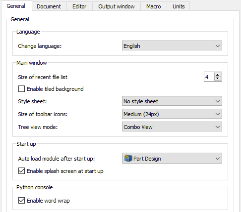
Ta sekcja menu konfiguracji zawiera 6 zakładek: Ogólne, Dokument, Edytor, Okno wyjściowe, Makro i Jednostki.
Informacje ogólne
W zakładce Ogólne możesz wprowadzić następujące dane:
| Nazwa | Opis |
|---|---|
| Zmień język | Wybierz język interfejsu użytkownika FreeCAD. |
| Rozmiar aktualnej listy plików | Określić, ile plików powinno znajdować się na liście ostatnio używanych plików. |
| Włączenie kafelkowego tła | Jeśli jest zaznaczone, tło głównego okna FreeCAD będzie domyślnie składać się z tych obrazów: 
Opcja ta działa tylko wtedy, gdy zaznaczono opcje w Style sheet/No style sheet. Obraz można zmienić poprzez dodanie folderów Gui/Images do lokalizacji %APPDATA%/FreeCAD (na Windows), $HOME/.FreeCAD (dla Linux) lub $HOME/Library/Preferences/FreeCAD (dla MacOS). Umieść tam plik nazwany background.png i odznacz/odznacz opcję, aby zobaczyć zmiany. |
| Styl arkusza | Wybór motywu dla wyglądu programu. Arkusze stylów określają, jak wygląda interfejs użytkownika FreeCAD. |
| Rozmiar ikon paska narzędzi | Wybór rozmiaru ikon na pasku narzędzi. |
| Po uruchomieniu załaduj utomatycznie moduł | Wybór, jakie Środowisko pracy będzie używane bezpośrednio po uruchomieniu programu FreeCAD |
| Wlącz ekran powitalny przy uruchamianiu | Gdy to pole wyboru jest zaznaczone, podczas uruchamiania wyświetlany jest ekran powitalny programu FreeCAD.
Obraz ekranu powitalnego można zmienić poprzez dodanie folderu Gui/Images w lokalizacji %APPDATA%/FreeCAD (gdzie %APPDATA% jest specyficznym dla użytkownika katalogiem aplikacji FreeCAD systemu operacyjnego). Umieść tam plik nazwany splash_image.png i uruchom ponownie FreeCAD, aby zobaczyć nowy ekran powitalny. |
| Włacz zawijanie wierszy | Słowa zostaną zawinięte, gdy przekroczą dostępną przestrzeń poziomą w konsoli Pythona. Konsola jest wyświetlana za pomocą menu Widok → Panele → Konsola Python. |
Dokument
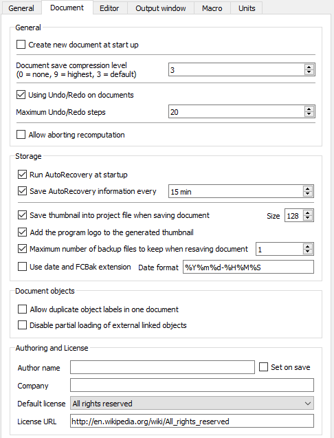
W zakładce Dokument można wybrać następujące opcje:
| Nazwa | Opis |
|---|---|
| Utwórz nowy dokument w trakcie uruchamiania | Jeśli opcja jest zaznaczona, FreeCAD utworzy nowy dokument po uruchomieniu. |
| Stopień kompresji podczas zapisu | Specyfikacja poziomu kompresji dla plików {FCStd. Pliki FCStd} są plikami skompresowanymi w formacie ZIP. Dlatego możesz zmienić ich rozszerzenie {.FCStd na .zip} i otworzyć je za pomocą programu do archiwizacji ZIP. |
| Użyj cofnij/ponów w dokumentach | Jeśli to pole jest zaznaczone, wszystkie zmiany w dokumentach są zapisywane tak, aby można je było cofnąć/odtworzyć. |
| Maksymalna ilość króków cofnij/ponów | Określa, ile kroków Cofnij/Zmień powinno zostać zarejestrowanych (0-99). |
| Uruchomienie funkcji autoodzyskiwania przy starcie | Jeśli jest dostępny plik odzyskiwania, FreeCAD automatycznie uruchomi funkcję odzyskiwania pliku w momencie jego uruchomienia. W ten sposób pliki mogą zostać odtworzone, jeśli wystąpi awaria. |
| Zapisz informacje autoodzyskiwania | Określ, jak często będzie zapisywany plik odzyskiwania. |
| Zapisywanie miniatur do pliku projektu, przy zapisywaniu dokumentu | Jeśli to pole jest zaznaczone, po zapisaniu dokumentu zostanie również zapisana miniaturka. Miniaturka będzie wyświetlana na przykład na liście ostatnio zapisanych plików Środowiska pracy Start. |
| Dodaj logo programu do wygenerowanej miniaturki. | Jeśli to pole jest zaznaczone, logo programu FreeCAD |
| Maksymalna liczba plików kopii zapasowych do zachowania podczas zapisywania dokumentu | Jeśli to pole jest zaznaczone, pliki kopii zapasowej będą zapisywane podczas zapisywania dokumentu. Można określić, ile plików kopii zapasowych będzie przechowywanych. Zawierają one wcześniej zapisaną wersję dokumentu. Pierwszy plik kopii zapasowej będzie miał rozszerzenie .FCStd1, drugi .FCStd2 i tak dalej. |
| Wyłącz częściowe wczytywanie połączonych obiektów zewnętrznych. | Włączyć częściowe załadowanie zewnętrznego dokumentu połączonego. Gdy jest to włączone, tylko obiekty referencyjne i ich zależności będą ładowane, gdy połączony dokument jest automatycznie otwierany razem z dokumentem głównym. Częściowo załadowany dokument nie może być edytowany. Kliknij dwukrotnie ikonę dokumentu w widoku drzewa, aby załadować go w całości. Bardziej szczegółowe objaśnienie funkcji można znaleźć na stronie Assembly3 documentation page |
| Zezwalaj na dublowanie etykiet obiektów w jednym dokumencie | Jeśli to pole jest zaznaczone, obiekty mogą mieć tę samą etykietę/nazwę. Na przykład różne części lub elementy mogą mieć wtedy identyczną nazwę w obrębie tego samego dokumentu. |
| Nazwa autora | Wszystkie powstające dokumenty otrzymają określoną nazwę autora. Pole autora należy pozostawić puste na wypadek gdy autor ma pozostać anonimowy. Jeżeli zaznaczona jest opcja Ustaw przy zapisie, pole Last modified by zostanie ustawione na określonego autora w trakcie zapisywania pliku. Informacje te można wyświetlić za pomocą menu Plik → Informacje o projekcie. |
| Nazwa firmy | Wszystkie utworzone dokumenty otrzymają podaną nazwę firmy. |
| Licencja domyślna | Wybór domyślnej licencji dla nowych dokumentów. W przypadku wstępnie zdefiniowanej licencji link URL licencji zostanie automatycznie ustawiony. Wybierz Inne, aby uzyskać licencję własną lub specjalną. |
| URL licencji | Wskazanie adresu URL opisującego licencję wybraną w polu Licencja domyślna |
Edytor
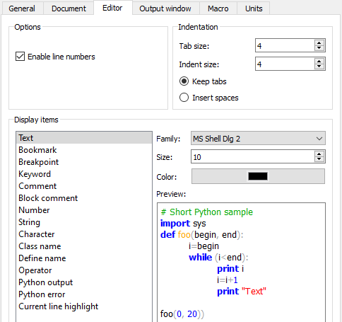
Ustawienia edytora preferencji mają wpływ na zachowanie edytora makr. Edytor ten można otworzyć za pomocą menu Makro → Makra... → Edycja/tworzenie.
The color and font settings also affect the Python console. This console is shown using the menu View → Panels → Python console.
In the Editor tab you can specify the following:
| Name | Description |
|---|---|
| Display Items | Selection of the code type. The color and font settings will be applied to the selected type. The result can be seen in the Preview field. |
| Family | Specification of the font family that should be used for the selected code type |
| Size | Specification of the font size that should be used for the selected code type |
| Enable line numbers | If checked, the code lines will be numbered |
| Tab size | Specification of the tabulator raster (how many spaces). If it is for example set to '6', pressing Tab will jump to character 7 or 13 or 19 etc., depending the current cursor position. This setting is only used if Keep tabs is selected. |
| Indent size | Specification of how many spaces will be inserted when pressing Tab. This setting is only used if Insert spaces is selected. |
| Keep tabs | If selected, pressing Tab will insert a tabulator with the raster defined by Tab size |
| Insert spaces | If selected, pressing Tab will insert the amount of spaces defined by Indent size |
Okno wyjściowe
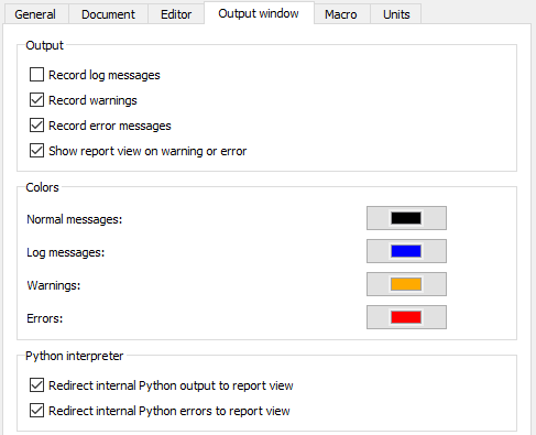
The output preferences affect the behavior of the Report view.
In the Output tab you can specify the following:
| Name | Description |
|---|---|
| Record log messages | If checked, also log messages will be recorded. They will be output in the Report view panel with the color set in Log messages. This panel is shown using the menu View → Panels → Report view. |
| Record warnings | If checked, warnings will be recorded. They will be output in the Report view panel with the color set in Warnings. |
| Record error messages | If checked, error messages will be recorded. They will be output in the Report view panel with the color set in Errors |
| Show report view on error or warning | If checked, report view panel will show up automatically as soon as an error or warning is logged. |
| Normal messages | Specification of the font color for normal messages in the Report view panel. |
| Log messages | Specification of the font color for log messages in the Report view panel. |
| Warnings | Specification of the font color for warning messages in the Report view panel. |
| Errors | Specification of the font color for error messages in the Report view panel. |
| Redirect internal Python output to report view | If checked, internal Python output will be redirected from the Python console to the Report view panel. The Python console is shown using the menu View → Panels → Python console |
| Redirect internal Python errors to report view | If checked, internal Python error messages will be redirected from the Python console to the Report view panel. |
Makro
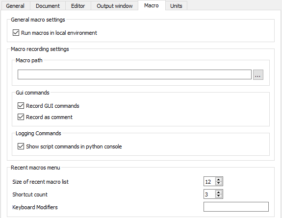
These options control certain aspects of running macros.
In the Macro tab you can specify the following:
| Name | Description |
|---|---|
| Run macros in local environment | If checked, variables defined by macros are created as local variables, otherwise as global Python variable |
| Macro path | Specification of a path to macro files |
| Recording GUI commands | If checked, recorded macros will also contain user interface commands |
| Record as comment | If checked, recorded macros will also contain user interface commands but as comments. This is useful if you don't want to execute visible actions when running the macro but to see what could be done visibly. |
| Show script commands in python console | If checked, the commands executed by the macro scripts are shown in the Python console. This console is shown using the menu View → Panels → Python console. |
Jednostki
This tab configures how Units are shown.
In the Units tab you can specify the following:
| Name | Description |
|---|---|
| User system | Selection of a unit system that should be used for all parts of FreeCAD |
| Number of decimals | The number of decimals that should be shown for numbers and dimensions in FreeCAD |
| Minimum fractional inch | Minimum fractional inch that should be displayed. This setting is only available if the unit system Building US (ft-in/sqft/cuft) is used. |
Ustawienia ekranu
This preferences section has two general tabs, 3D View and Colors, and further tabs depending in the used workbenches.
3D View
This tab is always available, and controls certain characteristics of the 3D view.
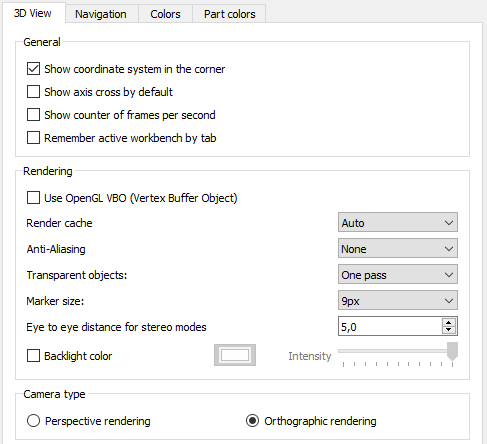
In the 3D View tab you can specify the following:
| Name | Description |
|---|---|
| Show coordinate system in the corner | If checked, the main coordinate system will always be shown at the lower right in opened files |
| Show counter of frames per second | If checked, the time needed for the last operation and the resulting frame rate will always be shown at the lower left in opened files |
| Show navigation cube | If checked, the navigation cube will always be shown at the selected Corner in opened files |
| Use OpenGL Vertex Buffer Object | If checked, Vertex Buffer Objects (VBO) will be used. A VBO is an OpenGL feature that provides methods for uploading vertex data (position, normal vector, color, etc.) to the graphics card. VBOs offer substantial performance gains because the data resides in the graphics memory rather than the system memory and so it can be rendered directly by GPU. For more background info see this webpage. |
| Render Cache introduced in version 0.19 | "Render Cache" or "Render Acceleration" is explained in more detail in Link#render-caching. There are 3 options:
|
| Enable animation | If checked, rotations can be animated. If for example the 3D Navigation set CAD is used and the mouse is moved while the scroll wheel and the right mouse button is pressed, parts are rotated. If one keeps the mouse moving while releasing e.g. the right mouse button, the rotation will continue as animation. To end the animation left-click with the mouse. |
| 3D Navigation | Selection of a navigation settings set. To see what each set defines, select a set and press the button Mouse.... |
| Orbit style | Selection of the rotation orbit style. When viewing a part in the x-y plane an being in the rotation mode of the 3D navigation, the difference is: If Trackball is selected, moving the mouse horizontally will rotate the part around the y-axis, if Turntable is selected the part will be rotated around the z-axis. |
| Anti-Aliasing | Selection if and what kind of multisample anti-aliasing is used |
| New Document Camera Orientation | Selection of the camera orientation for new documents |
| New Document Scale | Affects the initial "zoom level" of camera for new documents. The value you set is the diameter of a sphere that fits in 3D view. Default is 100 mm, convenient for objects like boxes for Arduino. It also sets initial size of origin features (base planes in a new PartDesign Body). |
| Zoom at cursor | If checked, zoom operations will be performed at the position of the mouse pointer. Otherwise zoom operations will be performed at the center of the current view. The Zoom step defines how much will be zoomed. A zoom step of '1' means a factor of 7.5 for every zoom step. |
| Invert zoom | If checked, the direction of zoom operations will be inverted. |
| Disable touchscreen tilt gesture | If checked, the tilting gesture will be disabled for pinch-zooming (two-finger zooming). This only affects the 3D Navigation set Gesture. |
| Drag at cursor | If checked, rotations in 3D will use the current cursor position as center for the rotation. Otherwise always the center of the screen will be used. |
| Marker size | Selection of the size of vertices (points) in the Sketcher workbench. The clickable area of points can be additionally enlarged by increasing Pick radius (on Colors tab). |
| Eye to eye distance for stereo modes | Specification of the eye-to-eye distance used for stereo projections. The specified value is a factor that will be multiplied with the bounding box size of the 3D object that is currently displayed. |
| Enable backlight color | If checked, backlight is enabled with the defined color. Backlight is used for rendering back sides of faces (usually, you don't see them in solids, unless you slice one with a clipping plane, or if the faces aren't oriented correctly). It is only active for objects whose Lighting property (on View tab) is set to "One side". If disabled, back sides of faces of objects in "One side" lighting mode will be black. |
| Intensity of backlight | Specification of the intensity of the backlight. This setting is only enabled if Enable backlight color is checked. |
| Camera type | Selection of the camera projection type.
|
Zabarwienie
This tab is always available.
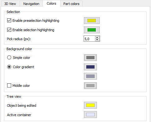
In the Colors tab you can specify the following:
| Name | Description |
|---|---|
| Enable preselection highlighting | If checked, preselection is turned on and will be highlighted by the specified color. Preselection means that for example edges in parts will be highlighted while hovering with the mouse over them to indicate that they can be selected. |
| Enable selection highlighting | If checked, selection highlighting is turned on and the specified color will be used for it |
| Pick radius | Sets the area for picking elements in 3D view. Larger value makes it easier to pick things, but can make some small features impossible to select. |
| Simple color | If selected, the background for parts will have the selected color |
| Color gradient | If selected, the background for parts will have the selected color gradient |
| Middle color | Is only enabled if Color gradient is selected. If checked, the color gradient will get the selected color as middle color. |
| Object being edited | Selection of the background color for objects in the tree view that are currently edited |
| Active container | Selection of the background color for active containers in the tree view. For example if there are several parts in the tree view and one part is toggled as active body, it will get the selected background color in the tree view. |
Kolory wyświetlanych elementów
This tab is only shown if you are in the Part or PartDesign Workbench or if you have been in these workbenches before.
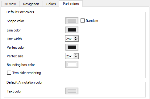
In the Part colors tab you can specify the following:
| Name | Description |
|---|---|
| Default shape color | Selection of the default color for new shapes. If the option Random shape color is set, a random color is used instead. |
| Default line color | Selection of the default line color for new shapes |
| Default line width | Specification of the default line thickness for new shapes |
| Default vertex color | Selection of the default color for new vertices |
| Default vertex size | Specification of the default size for new vertices |
| Bounding box color | Selection of the color of bounding boxes in the 3D view |
| Default text color | Selection of the default text color for document annotations. There is currently no dialog to add annotations to documents. Annotations can only be added using the Python console with this command:
This console is shown using the menu View → Panels → Python console. |
Mesh view
This tab is only shown if you are in the Mesh Workbench or if you have been in this workbench before.
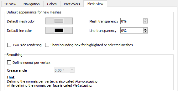
In the Mesh view tab you can specify the following:
| Name | Description |
|---|---|
| Default mesh color | Selection of the default color for new meshes |
| Default line color | Selection of the default line color for new meshes |
| Mesh transparency | Specification of the default mesh transparency for new meshes |
| Line transparency | Specification of the default line transparency for new meshes |
| Two-side rendering | If checked, the bottom side of the surface will be rendered the same way than the top side. If not checked, it depends on the option Enable backlight color (see section 3D view). Either the backlight color will be used or black. |
| Show bounding-box for highlighted or selected meshes | If checked, a yellow bounding box will be displayed for highlighted or selected meshes. |
| Define normal per vertex | If checked, Phong shading is used, otherwise flat shading. Shading defines the appearance of surfaces.
With flat shading the surface normals are not defined per vertex that leads to a unreal appearance for curved surfaces while using Phong shading leads to a smoother appearance. |
| Crease angle | The crease angle is a threshold angle between two faces. It can only be set if the option Define normal per vertex is used.
|
Import-Export settings
The Import-Export settings affect how files are imported and exported to and from FreeCAD. They are described in the page Import Export Preference.
Workbench preferences
Preferences for the more common workbenches are linked below. Some workbenches have no preferences. Other optional workbenches may not be listed.
- Arch Preferences
- Draft Preferences
- Drawing Preferences (brak)
- Fem Preferences
- Image Preferences (brak)
- Inspection Preferences (brak)
- Mesh Design Preferences (brak)
- OpenSCAD Preferences
- Part Preferences (brak)
- PartDesign Preferences
- Path Preferences
- Plot Preferences (brak)
- Points Preferences (brak)
- Raytracing Preferences
- Reverse Engineering Preferences (brak)
- Robot Preferences (brak)
- Ship Preferences (brak)
- Sketcher Preferences
- Spreadsheet Preferences (brak)
- Start Preferences
- Surface Preferences (brak)
- TechDraw Preferences
- Test Framework Preferences (brak)
- Web Preferences (brak)
External workbenches
- Jak zacząć
- Instalacja: Pobieranie programu, Windows, Linux, Mac, Dodatkowych komponentów, Docker, AppImage, Ubuntu Snap
- Podstawy: Informacje na temat FreeCAD, Interfejs użytkownika, Profil nawigacji myszką, Metody wyboru, Nazwa obiektu, Edytor ustawień, Środowiska pracy, Struktura dokumentu, Właściwości, Pomóż w rozwoju FreeCAD, Dotacje
- Pomoc: Poradniki, Wideo poradniki
- Środowiska pracy: Strona Startowa, Architektura, Assembly, CAM, Rysunek Roboczy, MES, Inspekcja, Siatka, OpenSCAD, Część, Projekt Części, Punkty, Inżynieria Wsteczna, Robot, Szkicownik, Arkusz Kalkulacyjny, Powierzchnia 3D, Rysunek Techniczny, Test Framework
