MES: Ścinanie bloku kompozytowego
| Temat |
|---|
| Analiza metodą elementów skończonych |
| Poziom trudności |
| Początkujący/średnio zaawansowany |
| Czas wykonania |
| 30 minut |
| Autorzy |
| HarryvL |
| Wersja FreeCAD |
| 0.17.12960 lub nowszy |
| Pliki z przykładami |
| Nie dołączono |
| Zobacz również |
| - |
Wprowadzenie
W tym przykładzie przeanalizujemy deformację postaciową kompozytowego bloku składającego się ze sztywnego rdzenia osadzonego w miękkiej matrycy. Zademonstrowane będzie użycie narzędzi BooleanFragments i CompoundFilter do utworzenia brył dla bloku i matrycy z dwóch współśrodkowych sześcianów. To podejście zapewnia możliwość przypisania obszarów siatki, materiałów i warunków brzegowych osobno dla bloku i otaczającej go matrycy. Do wybrania wewnętrznych obszarów wykorzystamy makro autorstwa Markusa Hovorki (https://github.com/drhooves/SelectionTools). Wyniki z solvera CalculiX wyraźnie pokazują wpływ sztywnego rdzenia na odpowiedź bloku kompozytowego.
Geometria
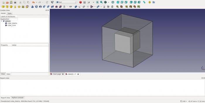
Najpierw utworzymy dwie współśrodkowe kostki, jedną o rozmiarze 10mm a drugą o rozmiarze 5mm. Robimy to w środowisku pracy "Część". Domyślnie sześcian jest umieszczony w środku układu współrzędnych [0,0,0]. więc mniejszy sześcian należy przeskalować i przesunąć poprzez zmianę ustawień w zakładce Dane panelu właściwości. Aby uczynić rdzeń widocznym, przezroczystość zewnętrznego bloku jest ustawiana na 50 w zakładce Widok panelu właściwości. Wynik jest pokazany poniżej.
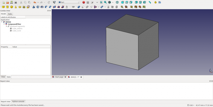
Następnie zaznaczmy dwa bloki w drzewie i utwórzmy obiekt BooleanFragments (Część → Rozdziel → Fragmentacja funkcją logiczną). W zakładce Dane panuelu właściwości zmień tryb na BryłaZłożona (CompSolid). Teraz zaznacz obiekt BooleanFragments w drzewie modelu i utwórz Filtr złożeń (Część → Złożenie → Filtr złożeń).
Siatka i obszary siatki
W środowisku pracy MES tworzymy kontener Analiza. Będzie on zawierał wszystkie definicje wymagane do analizy w solverze CalculiX i jej wyniki. Zauważ, że ten kontener Analiza musi być aktywowany (kliknij prawym przyciskiem myszy i wybierz "Aktywuj analizę") przy każdym ponownym wczytaniu pliku lub po przełączeniu się z innej analizy. Aby rozpocząć proces generowania siatki, zaznacz obiekt CompoundFilter w drzewie modelu i aktywuj okno dialogowe "Siatka → Siatka MES z kształtu przy pomocy generatora Gmsh". Opuść okno dialogowe klikając OK.
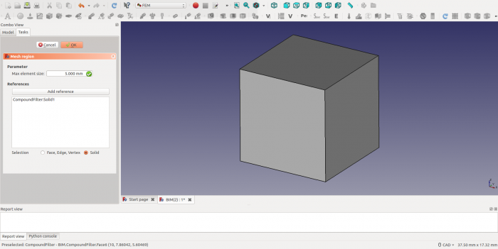
Obiekt siatki jest tworzony w drzewie modelu. Zaznacz go i utwórz Obszar siatki poprzez "Siatka → Obszar siatki MES". Otwórz okno dialogowe dla tego obszaru siatki klikając na nim dwukrotnie i zaznacz przycisk dla Solid. Następnie wciśnij przycisk "Dodaj odniesienie" i wybierz obiekt CompoundFilter w oknie graficznym. Powinno to dodać odniesienie do "CompoundFilter:Solid1" na liście obiektów obszaru siatki. Wreszcie, podaj maksymalny rozmiar elementów dla tego obszaru (tutaj 5mm). Opuść okno dialogowe klikając OK.
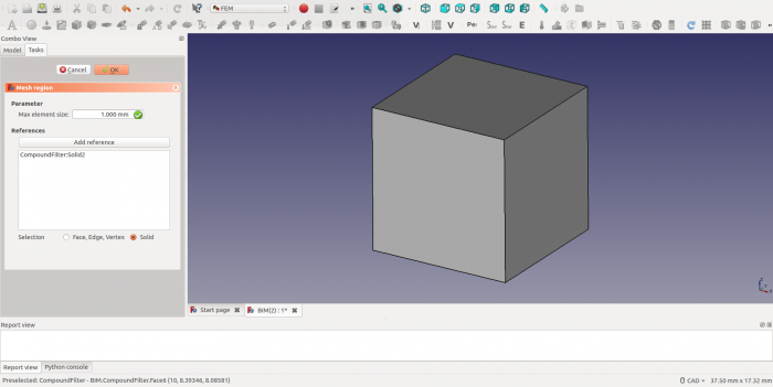
Następnie utwórz nowy obiekt siatki jak powyżej i użyj makra do wskazywania (skrót S, E) aby wybrać obiekt Cube_Core w oknie graficznym. Tym razem lista odniesień powinna pokazać "CompoundFilter:Solid2", jak poniżej. Wybieramy maksymalny rozmiar elementów 1mm.
Uwaga1: Wybór obiektu "CompoundFilter:Solid2" wymaga wskazania jednej z jego ścian.
Uwaga2: Jeśli masz problem z wyborem obiektu "CompoundFilter:Solid2", może to wynikać z pominięcia ustawienia trybu BryłaZłożona (CompSolid) w obiekcie BooleanFragments.
Przypisanie materiału
Materiał jest przypisywany do obszaru siatki poprzez obiekt SolidMaterial. W tym przykładzie przypisujemy dwa materiały, jeden dla matrycy i jeden dla rdzenia.
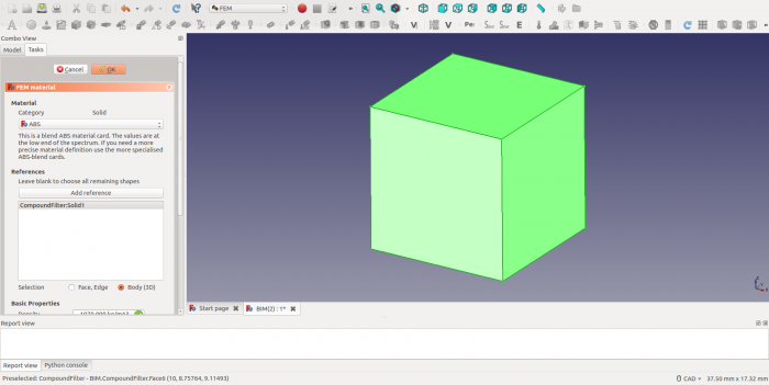
Start by selecting the CompoundFilter in the object tree. Then create a SolidMaterial object via menu option "Model → FEM material for solid". Open the dialog and tick the radio button for Solid, press "Add Reference" and select the CompoundFilter object from the Graphical Window. The reference list should now show "CompoundFilter:Solid1", as before. We assign ABS material to the Matrix, with a Young's modules approximately 1% that of steel.
Repeat the above procedure for the Core ("CompoundFilter:Solid2") with the help of the selection macro. This time we assign CalculiX-Steel, which is much stiffer than the ABS material for the Matrix.
Sliding Support
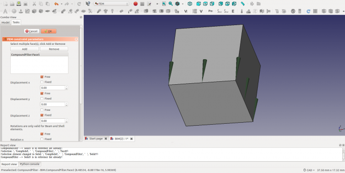
To create a "Simple Shear" condition for the composite block the deformations at the boundaries need to be unconstrained. To achieve this, the block is placed on a sliding support. This leaves three degrees of freedom in the plane of the support (2 translations and a rotation) and those will be constrained later. (Note: as the plane prevents warping of the face, it still induces a minor constraint, which could be eliminated by a different choice of boundary conditions). To create a sliding boundary condition add a FemConstraintDisplacement object (Model → Mechanical Constraints → Constraint displacement). With the dialog box open first select the face to which the boundary conditions is to be applied and then click the Add button. As the block is allowed to slide in the x-y plane, only the "Fixed" radio button for "Displacement z" is selected and the other radio buttons are all left as "Free".
Fixed Nodes
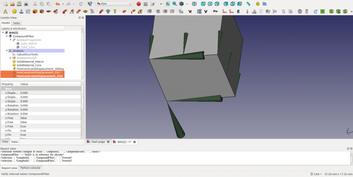
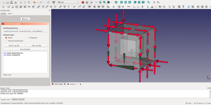
To prevent rigid body motion in the plane of sliding, three independent degrees of freedom need to be eliminated. To achieve this, one vertex in the plane of sliding is constrained in x and y direction (eliminating 2 degrees of freedom) and one vertex is fixed in the x direction (eliminating the last degree of freedom). For this purpose two additional FemConstraintDisplacement objects are created and the result is shown below.
Shear Forces
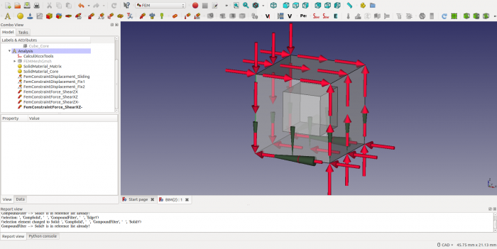
The final step in the Analysis definition is the application of loads. To create a Simple Shear condition, a set of shear loads is applied as shown below. Each load is chosen as 1000 N and considering the directions of application, force and moment equilibrium is achieved for all translation and rotional degrees of freedom. In FC this requires addition of four FemConstraintForce objects (Model → Mechanical Constraints → Constraint force) - one for each face. With the dialog box open first press the Add Reference button and then select the face to which the boundary condition is to be applied (Note: this is a different sequence than with FemConstraintDisplacement). By default, this creates a set of forces perpendicular to the face (i.e. a normal force). To change this to a shear force, press the direction button and select a cube edge that runs in the desired direction. If the resulting force points in opposite direction of what is required, then select the radio button for "Reverse direction".
CalculiX Analysis
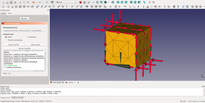
Now all mesh regions, material and boundary conditions have been defined we are ready to analyse the deformation of the block with CalculiX. Activate the Analysis by right clicking "Activate analysis", open the CalculiX dialog by double clicking the CalculiXccxTools object and select a directory for the temporary files created by both FC and CCX. Write CCX Input file and check for any warning or error messages.
After that the analysis can be started by pressing the RunCalculiX button. If all goes well, the CCX output window should show the following messages.
CalculiX Results
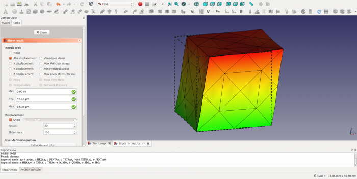
Upon completion of the analysis double click the "CalculiX_static_results" object and select the "Abs displacement" option. The maximum displacement of ~ 0.08mm will show up in the relevant output box. As the maximum displacement is relatively small compared to the dimensions of the block (<1% of the block size), the displacements need to be scaled up. This can be done under the heading "Displacement" by ticking the "Show" radio button and scaling the displacement by a factor of -say- 20. The maximum displacement will now be exaggerated to approximately 20% of the box size. After closing the dialog window, the deformed mesh can be made visible again by highlighting the Result_mesh object and pressing the space bar.
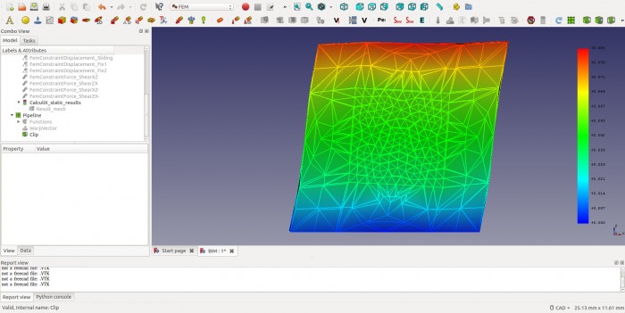
To investigate the deformation of the core we have to slice the block. This can be done by creating a clip filter. To activate this functionality, we first need to create a "post processing pipeline" by highlighting the "CalculiX_static_results" object and choosing "Results → Post Pipeline from Result" from the menu. Next, with the Pipeline selected create a Warp Filter (Results → Warp filter), set Vector=Displacement and Value=20 to scale the displacement and Display Mode = "Surface with Edges", Coloring Field = "Displacement", Vector = "Magnitude" to show colored displacement contours. Press Apply and OK. As a final step add a Clip Filter (Results → Clip filter) and create a plane with origin [5.0,2.5,5.0] and normal [0,1,0], i.e. at a core face with normal in the y-direction. Tick the "Cut Cells" radio button to create a flat surface. As before set Display Mode = "Surface with Edges", Coloring Field = "Displacement", Vector = "Magnitude" to show colored displacement contours. Press Apply and OK. Finally switch the Warp Filter to invisible to only show the cut block.
From the result it is clear that the core remains largely undeformed and helps to resist the deformation of the soft matrix (compare the shear angle of the blue colored part to that of the green colored part). What it also highlights though is that under Simple Shear conditions the faces of the composite block do warp, implying that the sliding boundary condition at the base of the cube does provide an undue constraint.
Further work
The following challenges may be interesting to take up as a further exercise:
1) Correct for the undue constraint imposed by the sliding boundary condition
2) Try and create contact boundary conditions between the core and the matrix to see if separation occurs
The FC file for this tutorial is attached below as a starting point.
https://forum.freecadweb.org/viewtopic.php?f=18&t=26517&start=20
Have fun !
- Materiał: Bryła, Ciecz, Nieliniowy materiał mechaniczny, Materiał zbrojony (beton), Edytor materiału
- Geometria elementu: Geometria elementu, Obrót w okół osi, Geometria elementu 2D, Element przepływu
Wiązania
- Elektromagnetyczne: Potencjał elektryczny, Gęstość prądu, Magnetyzacja
- Geometryczne: Obrót w płaszczyźnie, Zapis wyników z przekroju, Zdefiniuj odkształcenie
- Mechaniczne: Zdefiniuj przytwierdzenie, Zdefiniuj przemieszczenie, Zdefiniuj kontakt, Zdefiniuj powiązanie, Wiązanie sprężyny, Zdefiniuj siłę, Zdefiniuj obciążenie ciśnieniem, Zdefiniuj siłę odśrodkową, Zdefiniuj obciążenie ciężarem własnym
- Termiczne: Warunek początkowy temperatury, Zdefiniuj strumień ciepła, Zdefiniuj temperaturę, Zdefiniuj objętościowe źródło ciepła
- Zmieniające wiązania: Zdefiniuj przenikalność elektryczną próżni
- Siatki: Siatka Netgen, Siatka GMSH, Warstwa graniczna siatki, Obszar siatki, Grupa siatki, Utwórz zestaw węzłów, Siatka MES na obiekt środowiska Siatka
- Solver: Narzędzia CalculiX, Elmer, Mystran, Z88; Równania: Elastyczności, Elektrostatyczne, Siły elektrostatycznej, Magnetodynamiczne, RMagnetodynamiczne 2D, Przepływu, Strumienia, Ciepła; Solver: Kontrola pracy solvera, Uruchom solver
- Wyniki: Oczyszczanie z wyników, Prezentacja wyników; Postprocessing: Zastosuj zmiany, Prezentacja graficzna, Filtr rozpraszający, Skalarny filtr obcinający, Filtr odcięcia funkcji, Filtr odcięcia obszaru, Filtr konturów, Filtr danych wzdłuż linii, Wykres liniowości naprężeń, Filtr obcinania danych w punkcie, Utwórz funkcję, Filtr funkcji płaszczyzny, Filtr funkcji sfery, Filtr funkcji walca, Filtr funkcji prostopadłościanu
- Dodatkowe: Konfiguracja, Instalacja środowiska MES, Siatka, FEM Solver, CalculiX, Beton, Rodzaje elementów
- Jak zacząć
- Instalacja: Pobieranie programu, Windows, Linux, Mac, Dodatkowych komponentów, Docker, AppImage, Ubuntu Snap
- Podstawy: Informacje na temat FreeCAD, Interfejs użytkownika, Profil nawigacji myszką, Metody wyboru, Nazwa obiektu, Edytor ustawień, Środowiska pracy, Struktura dokumentu, Właściwości, Pomóż w rozwoju FreeCAD, Dotacje
- Pomoc: Poradniki, Wideo poradniki
- Środowiska pracy: Strona Startowa, Architektura, Assembly, CAM, Rysunek Roboczy, MES, Inspekcja, Siatka, OpenSCAD, Część, Projekt Części, Punkty, Inżynieria Wsteczna, Robot, Szkicownik, Arkusz Kalkulacyjny, Powierzchnia 3D, Rysunek Techniczny, Test Framework
