FEM ConstraintForce/pl: Difference between revisions
(Updating to match new version of source page) |
(Updating to match new version of source page) |
||
| Line 2: | Line 2: | ||
{{UnfinishedDocu{{#translation:}}}} |
{{UnfinishedDocu{{#translation:}}}} |
||
{{Docnav |
{{Docnav |
||
|[[ |
|[[FEM_ConstraintSpring|Constraint spring]] |
||
|[[FEM_ConstraintPressure|Constraint pressure]] |
|[[FEM_ConstraintPressure|Constraint pressure]] |
||
|[[FEM_Workbench|FEM]] |
|[[FEM_Workbench|FEM]] |
||
|IconL= |
|IconL=FEM_ConstraintSpring.svg |
||
|IconR=FEM_ConstraintPressure.svg |
|IconR=FEM_ConstraintPressure.svg |
||
|IconC=Workbench_FEM.svg |
|IconC=Workbench_FEM.svg |
||
| Line 46: | Line 46: | ||
{{Docnav |
{{Docnav |
||
|[[ |
|[[FEM_ConstraintSpring|Constraint spring]] |
||
|[[FEM_ConstraintPressure|Constraint pressure]] |
|[[FEM_ConstraintPressure|Constraint pressure]] |
||
|[[FEM_Workbench|FEM]] |
|[[FEM_Workbench|FEM]] |
||
|IconL= |
|IconL=FEM_ConstraintSpring.svg |
||
|IconR=FEM_ConstraintPressure.svg |
|IconR=FEM_ConstraintPressure.svg |
||
|IconC=Workbench_FEM.svg |
|IconC=Workbench_FEM.svg |
||
Revision as of 08:12, 20 September 2021
Ta dokumentacja nie jest ukończona. Prosimy o pomoc w tworzeniu dokumentacji.
Strona Model polecenia GUI wyjaśnia jak powinny być dokumentowane polecenia. Przejrzyj stronę Category:UnfinishedDocu, aby zobaczyć więcej niekompletnych stron, takich jak ta. Zobacz stronę Category:Command Reference aby poznać wszystkie komendy.
Zobacz stronę wytycznych Wikidla FreeCAD aby dowiedzieć się, jak edytować strony Wiki, i przejdź do strony Pomóż w rozwoju FreeCAD, aby dowiedzieć się o innych sposobach, w jakie możesz wnieść swój wkład.
|
|
| Menu location |
|---|
| Model → Mechanical Constraints → Constraint force |
| Workbenches |
| FEM |
| Default shortcut |
| None |
| Introduced in version |
| - |
| See also |
| FEM ConstraintPressure |
Description
This command applies a force of given value [N] to selected target geometry.
Usage
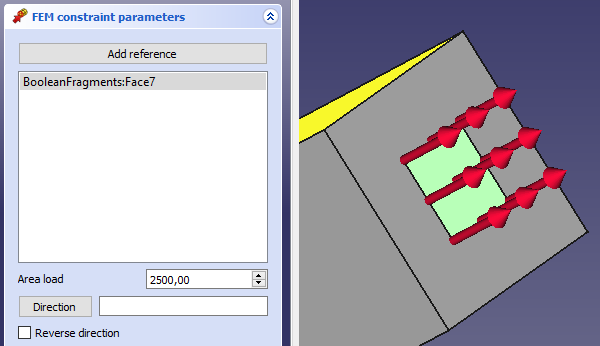
1) Applying a force in normal direction to a face
- If you have Mesh displayed, you need to hide it (select the mesh object and press spacebar or right click and select Hide item) and show the original model.
- Click on a face to which a force should be applied. It will appear in the list of geometrical objects.
- Fill in Line load with a force value in [N] (attention: Not in [N/m])
- Direction: In a typical case, you'll click this field empty to apply a force in normal direction to the face. You can revert the direction of the force by clicking Reverse direction. In other cases, you need to pick a face or plane, which is in normal to the force direction (it could differ from the face, to which the force is being applied)
- Click Close to finish the dialog and create
ConstraintForce object
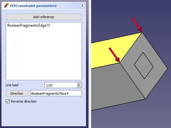
2) Applying a force in to line in selected direction
- In FEM workbench, click on
or select Model → Mechanical Constraints → Constraint force to open Force Constraint properties dialog
- If you have Mesh displayed, you need to hide it (select the mesh object and press spacebar or right click and select Hide item) and show the original model.
- Click on a line segment to which a force should be applied. It will appear in the list of geometrical objects.
- Fill in Area load with a force value in [N]
- Direction: Now, with line segment selected, it si likely that the force is applied in a wrong direction. We need to specify the direction by clicking the button Direction and then clicking a face pointing with its normal to the direction of the force (or reversed direction). Again, you can revert the direction of the force by clicking Reverse direction.
- In FEM workbench, click on
- Materiał: Bryła, Ciecz, Nieliniowy materiał mechaniczny, Materiał zbrojony (beton), Edytor materiału
- Geometria elementu: Geometria elementu, Obrót w okół osi, Geometria elementu 2D, Element przepływu
Wiązania
- Elektromagnetyczne: Potencjał elektryczny, Gęstość prądu, Magnetyzacja
- Geometryczne: Obrót w płaszczyźnie, Zapis wyników z przekroju, Zdefiniuj odkształcenie
- Mechaniczne: Zdefiniuj przytwierdzenie, Zdefiniuj przemieszczenie, Zdefiniuj kontakt, Zdefiniuj powiązanie, Wiązanie sprężyny, Zdefiniuj siłę, Zdefiniuj obciążenie ciśnieniem, Zdefiniuj siłę odśrodkową, Zdefiniuj obciążenie ciężarem własnym
- Termiczne: Warunek początkowy temperatury, Zdefiniuj strumień ciepła, Zdefiniuj temperaturę, Zdefiniuj objętościowe źródło ciepła
- Zmieniające wiązania: Zdefiniuj przenikalność elektryczną próżni
- Siatki: Siatka Netgen, Siatka GMSH, Warstwa graniczna siatki, Obszar siatki, Grupa siatki, Utwórz zestaw węzłów, Siatka MES na obiekt środowiska Siatka
- Solver: Narzędzia CalculiX, Elmer, Mystran, Z88; Równania: Elastyczności, Elektrostatyczne, Siły elektrostatycznej, Magnetodynamiczne, RMagnetodynamiczne 2D, Przepływu, Strumienia, Ciepła; Solver: Kontrola pracy solvera, Uruchom solver
- Wyniki: Oczyszczanie z wyników, Prezentacja wyników; Postprocessing: Zastosuj zmiany, Prezentacja graficzna, Filtr rozpraszający, Skalarny filtr obcinający, Filtr odcięcia funkcji, Filtr odcięcia obszaru, Filtr konturów, Filtr danych wzdłuż linii, Wykres liniowości naprężeń, Filtr obcinania danych w punkcie, Utwórz funkcję, Filtr funkcji płaszczyzny, Filtr funkcji sfery, Filtr funkcji walca, Filtr funkcji prostopadłościanu
- Dodatkowe: Konfiguracja, Instalacja środowiska MES, Siatka, FEM Solver, CalculiX, Beton, Rodzaje elementów
- Jak zacząć
- Instalacja: Pobieranie programu, Windows, Linux, Mac, Dodatkowych komponentów, Docker, AppImage, Ubuntu Snap
- Podstawy: Informacje na temat FreeCAD, Interfejs użytkownika, Profil nawigacji myszką, Metody wyboru, Nazwa obiektu, Edytor ustawień, Środowiska pracy, Struktura dokumentu, Właściwości, Pomóż w rozwoju FreeCAD, Dotacje
- Pomoc: Poradniki, Wideo poradniki
- Środowiska pracy: Strona Startowa, Architektura, Assembly, CAM, Rysunek Roboczy, MES, Inspekcja, Siatka, OpenSCAD, Część, Projekt Części, Punkty, Inżynieria Wsteczna, Robot, Szkicownik, Arkusz Kalkulacyjny, Powierzchnia 3D, Rysunek Techniczny, Test Framework


