Drawing View/pl: Difference between revisions
(Created page with "{{docnav/pl |New A3 landscape drawing |Annotation |Drawing Module |IconL=Drawing_Landscape_A3.png |IconC=Wor...") |
(Created page with "=== Kreator widoków rysunków === Aby automatycznie wygenerować arkusz rysunkowy z widokami standardowymi, użyj Macro_Automatic_drawing/pl|Makrodefinicja: Automatyczne ry...") |
||
| Line 48: | Line 48: | ||
=== |
=== Kreator widoków rysunków === |
||
Aby automatycznie wygenerować arkusz rysunkowy z widokami standardowymi, użyj [[Macro_Automatic_drawing/pl|Makrodefinicja: Automatyczne rysowanie]]. |
|||
To generate a drawing sheet with standard views automatically, use the [[Macro Automatic drawing|Automatic drawing Macro]]. |
|||
{{clear}} |
{{clear}} |
||
Revision as of 15:46, 1 July 2021
|
|
| Lokalizacja w menu |
|---|
| Drawing → Insert view in drawing |
| Środowisko pracy |
| Drawing, Complete |
| Domyślny skrót |
| brak |
| Wprowadzono w wersji |
| - |
| Zobacz także |
| Drawing Landscape A3 |
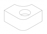
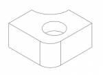
To narzędzie tworzy nowy widok wybranego obiektu w aktywnym arkuszu rysunkowym.
Użycie
Zaznacz obiekt w oknie widoku 3D lub w drzewie projektu, a następnie kliknij narzędzie Widok rysunku. Domyślnie zostanie umieszczony widok z góry przeskalowany w skali 1:1 (skala rzeczywista) w lewym górnym rogu strony. Może on nie być widoczny, jeśli jest zbyt mały lub zbyt duży dla strony.
A View object is added to the Page object in the Project tree. For subsequent views, a three-digit number will be appended to the name. Click on the arrow in front of the Page object to unfold it and display the views it contains.
If only the object is selected in the Project Tree, the view is added to the first page of the project. If you have multiple pages in your project please select the object and the page it should be added to. Then click on the icon to add the view to the selected page.
Modify an existing view
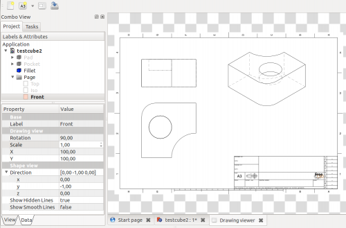
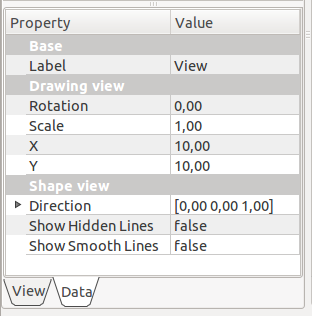
Unfold the Page object in the Project tree, and select the View. Its parameters can be edited in the Property View Data tab.


- Label: changes the view's label in the Project tree. You can also click on the View in the tree and right-click → Rename, or press F2.
- Rotation: rotates the view. For example, an isometric view will require a 60 degree rotation (see also Direction parameter below)
- Scale: sets the view scale.
- X: sets the view's horizontal position on the page in millimeters.
- Y: sets the view's vertical position on the page in millimeters. Please note that coordinate (0,0) is located at the top left of the page, so the higher the number, the lower in the page the view will be.
- Direction: changes the view direction. It is set by xyz values that define a vector normal to the page. Top view will be (0,0,1), and isometric will be (1,1,1). Values can be negative.
- Show Hidden Lines: toggles the hidden lines visibility on or off by selecting True or False.
- Show Smooth Lines: toggles the smooth lines visibility on or off by selecting True or False. Smooth lines are also called tangency edges. These edges indicate surface changes between tangent surfaces.
Kreator widoków rysunków
Aby automatycznie wygenerować arkusz rysunkowy z widokami standardowymi, użyj Makrodefinicja: Automatyczne rysowanie.
Other
If you are looking for persective-orthographic toggling in 3D view check Std PerspectiveCamera and Std OrthographicCamera
- Jak zacząć
- Instalacja: Pobieranie programu, Windows, Linux, Mac, Dodatkowych komponentów, Docker, AppImage, Ubuntu Snap
- Podstawy: Informacje na temat FreeCAD, Interfejs użytkownika, Profil nawigacji myszką, Metody wyboru, Nazwa obiektu, Edytor ustawień, Środowiska pracy, Struktura dokumentu, Właściwości, Pomóż w rozwoju FreeCAD, Dotacje
- Pomoc: Poradniki, Wideo poradniki
- Środowiska pracy: Strona Startowa, Architektura, Assembly, CAM, Rysunek Roboczy, MES, Inspekcja, Siatka, OpenSCAD, Część, Projekt Części, Punkty, Inżynieria Wsteczna, Robot, Szkicownik, Arkusz Kalkulacyjny, Powierzchnia 3D, Rysunek Techniczny, Test Framework

