Basic Part Design Tutorial 019: Difference between revisions
Edwilliams16 (talk | contribs) (→Center Hole: Clarify pocket location and TNP) |
Edwilliams16 (talk | contribs) (Combobox Length -> Dimension) |
||
| Line 384: | Line 384: | ||
# Select '''Sketch004'''. |
# Select '''Sketch004'''. |
||
# Select [[File:PartDesign_Pocket.svg|24px|link=PartDesign_Pocket]] [[PartDesign_Pocket|Pocket]] and configure the operation: |
# Select [[File:PartDesign_Pocket.svg|24px|link=PartDesign_Pocket]] [[PartDesign_Pocket|Pocket]] and configure the operation: |
||
## Select '''Type''' {{ComboBox| |
## Select '''Type''' {{ComboBox|Two Dimensions}}. |
||
## Assign '''8.50mm''' to '''Length''' and '''Length2''' values |
## Assign '''8.50mm''' to '''Length''' and '''Length2''' values |
||
## Click the {{Button|OK}} button. |
## Click the {{Button|OK}} button. |
||
# Select the newly created '''Pocket001''' and modify '''Refine''' property to '''True''' |
# Select the newly created '''Pocket001''' and modify '''Refine''' property to '''True''' |
||
''Note: Alternatively we could have used '''Type''' {{ComboBox| |
''Note: Alternatively we could have used '''Type''' {{ComboBox|Dimension}}, checked '''Symmetric to Plane''' and entered '''17 mm''' for the Length value'' |
||
This will result in: |
This will result in: |
||
Revision as of 19:42, 12 November 2022
| Topic |
|---|
| Modeling |
| Level |
| Beginner |
| Time to complete |
| Less than an hour |
| Authors |
| Carlo Dormeletti (onekk) Ed Williams (edwilliams16) |
| FreeCAD version |
| 0.19 or higher |
| Example files |
| [] |
| See also |
| None |
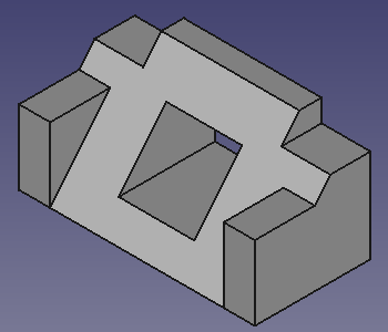
This tutorial introduces the new user to some of the tools and techniques used in the PartDesign Workbench. This tutorial is not a complete and comprehensive guide to the Part Design Workbench and many of the tools and capabilities are not covered. This tutorial will take user through the steps needed to model the part shown in the image below using sketches.
Author Note: This tutorial is work in progress, in this state it is tested only with FreeCAD version 0.20.1 for Linux. Screenshots are made for 0.20.1 too, but it should work without big problems even on 0.19.
As soon I find someone to review it for 0.19 I will made appropriate remarks if necessary for v0.19
Before You Begin
The Task
In this tutorial, you will be using the Part Design Workbench to create a 3D solid model of the part shown in the Drawing below, on which all of the necessary dimensions to complete this task are given. See Workbench Concepts for some conceptual background.
You will start by creating a core solid shape from a base Sketch and then build on that shape, adding what are known as Features.
These features will either add material to, or remove material from the solid by use of additional sketches and accompanying feature operations.
This Tutorial will not use every feature and tool available within the Part Design Workbench, but should use enough to give the user of this tutorial a basic foundation upon which to build their knowledge and skills.
This tutorial will provide detailed descriptions when it describes an operation for the first time; subsequent operations will have a more concise description. When in doubt, find the operation that contains the more detailed description. For instance, when creating a sketch for the first time the process of choosing the sketch Plane will be explained in detail, for subsequent sketches it will not.
Feel free to signal errors and problems in this forum thread:
New Part Design Tutorial for FC 019 and 020
The Part

Constructing The Part
Startup
First begin by making sure you are in PartDesign Workbench, selected from the drop-down menu. Once there, you will want to create a new document if you have not done so already. It is a good habit to save your work often, so first save the new document, giving it any name you choose.
All work in Part Design begins with a Body. Then we will build the solid inside the body by starting with a sketch.
Click on Create new body to create and activate a new Body Container. Note: this step can be omitted. When creating a sketch using Part Design|Sketch|Create Sketch, if no existing Body is found, a new one is automatically created and activated. This is not the case if you create a sketch using the Sketcher workbench, as sketches are useful in workbenches other than Part Design.
Master Sketch
You will create a master sketch, see Sketcher WorkBench for a more detailed explanation of the terminology used here.
The workflow follows one of the many possible ways to make the above design.
This example will use some techniques described in Advice for creating stable models.
- master sketch
- Named constraints are used to hold dimensions that can be readily referenced later in the model construction.
For instance, to change the model width from 53 mm, as in the technical drawing, to 55 mm we need only to modify the Length value of the appropriate named constraint in the master sketch and the whole model will modify accordingly. This is parametric design in action. - External Geometries are potentially subject to the Topological Naming Problem. We will be use them only when strictly necessary and will attempt to refer to the most stable elements available. Referring to edges or vertices of prior sketches is normally more stable than referencing edges or vertices of generated geometry.
Rationale
- The Master sketch contains the model's rectangular base shape and two named constraints that will be created to supply correct dimensions to other parts of the model:
- length that will contain 53mm. (The result of adding the 39mm dimension to the two 7mm "sides")
- width that will contain 26mm.
Notes
- If
Auto constraints in the Edit controls window is checked, some constraints will be applied automatically. Otherwise, you will need to apply them yourself.
- You exit a drawing tool either by right-clicking an empty area of the 3D view or by pressing the ESC. The mouse cursor should change to the standard arrow cursor. If you press ESC an additional time you will exit the sketch editing mode. To return to the editor either click on the Model tab and double-click the Sketch element in the tree, or right-click in the 3D view and select Edit sketch in the context menu.)
- If Sketcher's Solver detects a redundant constraint it will turn the sketch orange in color. Before further constraints are added, redundant constraints should be removed. (Redundant constraints are shown in the Task view - click on the blue reference and press DEL.)
- It's possible that some elements of the side panel, for instance the OK button may not be visible if the side panel is not wide enough.
You can make it wider by dragging its right border.
Place your mouse pointer over the border; when the pointer changes to a two-way arrow, press and hold the left mouse button and drag.

Sketch
- Click on
Create new sketch. This will create the sketch within the just created body. It will be named Sketch.
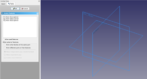
- A dialog like Fig: SK1 will open in Tasks tab on which you have to choose on which plane sketch will be attached.
- Select XY_Plane from the Combo view list.
- Press OK
- FreeCAD automatically:
- switches to Sketcher workbench
- opens the sketch in editing mode and you will see something like Fig: SK2.
Step1: Rectangle creation
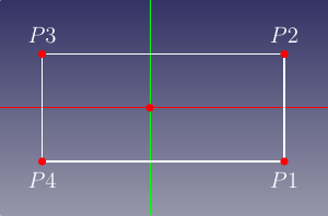

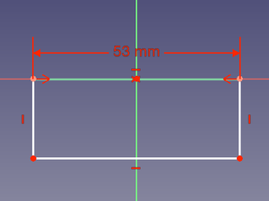

Click on Rectangle tool and start creating a rectangle this way:
- Create the rectangle roughly centered on Y axis resembling Fig: SKC1. Note:
- Don't place points on X axis as the Solver will automatically apply constraints that will create a problem later.
- The dimensions of the rectangle are unimportant at this point. They will be assigned using constraints in a later step.
- Once done, press ESC (or right-click) to exit "rectangle creation mode". "Rectangle creation mode" is indicated by this cursor appearance
 .
.
Step2: Horizontal constraint
Assign now horizontal distance constraint this way:
- Select the line defined by P2 to P3 in Fig: SKC1.
- Use the button
horizontal distance constraint this will make two things happen:
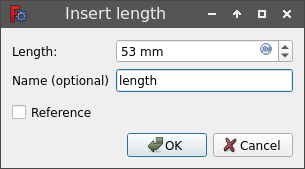
- Assign a Length = 53mm, and to be able to easily reference this dimension later a name is required: assign Name = length. (You are free to use the name of your choice. It need only be unique within the sketch.)
- Click OK.
- The result should resemble Fig: SKC2
Step3: Symmetrical constraint
To center the the top edge of the rectangle around the origin proceed as follows:
- Select points P2 and P3 of the rectangle.
- Select the origin of the sketch.
Note: the selection order of the points is important. - Use
Symmetric tool.
- You will end up with something that resembles Fig: SKC3.
- Making a good choice of origin of the model can simplify its construction, in this case by taking advantage of the part's reflection symmetry in a later steps.
Step5: Vertical constraint
You now assign a vertical distance constraint, using a procedure analogous to the prior horizontal distance constraint
- Select the line defined by P3 to P4 in Fig: SKC1.
- Click on
vertical distance constraint and assign:
- Length = 26 mm
- Name = width.
- Click OK.
- Result should resemble Fig: SKC4.
Step6: Close Sketch
Click on Close button in the Tasks tab to leave sketch edit mode.
Note the following:
- The lines on the sketch will become "bright green". (Assuming you have not modified the default color theme).
- The Solver messages window displays Fully constrained.
- If you now click on any line or vertex and try to drag it, it won't move.
Main Profile
You will create a new sketch that is holding the main profile.
Sketch001
- Click on
Create new sketch. Create it in YZ_Plane. FreeCAD will assign the name of Sketch001.
Step1: Polyline
- Use the
Polyline tool to make a shape like that in Fig: SP1;
- Follow the order of points indicated in the figure (It was not obtained using FreeCAD, but has the real appearance with default color theme).
- As in the first sketch you will assign proper constraints later to adjust the dimensions and exact shape (see note about Constraints below).
Step2: Constraints
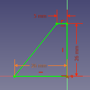
From Fig: SP1 you will see that FreeCAD has already applied some constraints:
- Top horizontal line has a
Horizontal Constraint applied.
- Right point of the top line has a
Point On Object Constraint applied.
- Left point of bottom horizontal line has another
Point On Object Constraint applied.
Note: It may be easier for a less-experienced user of Sketcher to make the initial drawing offset from the axes and then apply these constraints "by hand". For instance, just because two points appear to be coincident, doesn't mean they there is a coincidence constraint in place. Any constraint has to be explicit. When selecting vertices or lines with sketcher tools they will turn (default) green and any auto-constraints that will be applied will show beside the cursor.
- Select the line defined by points P2 and P3 and apply a
horizontal distance constraint and assign Length = 5 mm.
- Select the line defined by points P1 and P2 and apply a
vertical distance constraint and assign Length = 26 mm.
- Select the line defined by points P4 and P1 and apply a
horizontal distance constraint. For this value you will use a "Named constraint" using Expressions. To do so you have to press the little button on the dimensions
, and you will be presented with a new dialog window named Formula editor that contains an input field and a Result: label, similar to the image below:

Expression dialog
When you start typing in the cell, you will be presented with some autocompletions, the example shows<<Sketch>>.
- Select the right one for your design; in this case we want
<<Sketch>>.. Note the point after the "element name". - To select named constraint "width", you have to enter
Constraints.with the point. Here autocomplete works. - To add "length", as yet autocompletion is not available, so complete the cell to read
<<Sketch>>.Constraints.width. If all is good you should see in the cell Result: the correct value as in figure below:
Espression result good
Note the absence of any "red error message" and the correct value of the dimension is displayed in the Result field - Click OK to close Formula editor dialog.
- Click OK to close Insert length dialog.
At this point you should have a fully constrained sketch similar to Fig: SPFC.
Note the different colors between distance constraints assigned using expressions and those assigned specifying a length.
- Select the right one for your design; in this case we want
Step3: Close Sketch001
- Click on Close button in the Tasks tab to leave sketch edit mode.
Pad

Select Pad from the toolbar or from the Part Design menu.
This will give you a Pad dialog in the Task View.
Using that dialog, set its values accordingly to the following directions:
- For Type select
Dimension .
- For Length you will use again an Expression but this time you will enter
<<Sketch>>.Constraints.lengthin the field. - Select
Symmetric to plane.
Once that is done you will have a solid as shown in Fig: Pad
Features
With Pad you have obtained a solid.
Now it is time to add some Features to this solid.
These Features could be obtained in various ways, the way presented here is not the only way to achieve desired result.
Starting point is another time a Sketch.
Sketch002

- Hide the just created solid; Select it and hit Spacebar to hide.
- Click on
Create new sketch in XZ_Plane; Sketch will be named Sketch002.
Step1: Rectangle
- Select
Rectangle tool, and create a rectangle, do not create it near the axis, to avoid automatic constraints that will make difficult to move it in the correct position using External geometry tool.
Step2: Contraints
Apply these constraints:
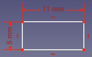
- Select one of the horizontal lines apply a horizontal distance constraint and a value of 11 mm.
- Select one of the vertical lines and give it a vertical distance constraint and a value of 5 mm.
You should obtain something similar to Fig: SK2.
Step3: Close Sketch002
- Click Close at top of the Tasks tab in the Combo View window.
Step:4 Make visible external geometries
To use an External geometry is necessary to have sketches to which we are "attaching" our geometry visible when you are modifying Sketch002.
- In the Treeview select Sketch and Sketch001 and make both visible using Spacebar.
Step5: Applying External geometries constraints
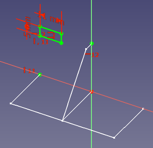
- Double click on Sketch002 to activate edit mode again and adjust the view so you have clearly visible the points as example like in Fig: SK2_1, this will ease subsequent steps.
Note: rectangle's initial position could be different on your sketch. - Select
External geometry tool, the cursor will became
 .
. - Select with this cursor point P1 in Fig: SK2_2, selected point will remain highlighted and in the Elements tab of Task Panel you will see that this element is shown File:Pd tut ext geom pt.png.
- Select with this cursor point P2 in Fig: SK2_2.
In the Elements tab of Task Panel you will see another element like the above. - Press ESC to terminate External Geometry selection. Cursor will return standard arrow pointer.
- Select point P1 and point P3 and apply a
Vertical Constraint.
Rectangle will be aligned with the vertical position of selected point. - Select point P2 and point P3 and apply a
Horizontal Constraint.
Rectangle will be aligned with the horizontal position the selected point.
Step4: Close Sketch002
- Click Close button at top of the Tasks tab in the Combo View window.
Pockets

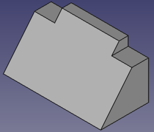
You have to subtract some material using the just created sketch that is positioned at one end. To make this operation you have to use Pocket tool from the toolbar or Part Design menu.
Using this tool is the opposite of the Pad tool. As the Pad tool adds material to the part, the Pocket tool removes material from the part.
- Select Pad and Unhide it.
- Select Sketch002.
- Select
Pocket and configure the operation:
You should have something that resemble Fig: PK1
Mirror
Instead of creating another sketch and pocketing it, we can take advantage of the model's mirror symmetry about the YZ_plane, and use Mirrored.
- Select “Pocket”.
- Click on the
Mirrored feature on the toolbar or from the Part Design menu.
A dialog will appear in the Combo View.
Sides
Sketch003


- Make Sketch visible as done before.
- Click on
Create new sketch and create the new sketch in XY_Plane; Sketch will be named Sketch003.
- Select
Rectangle tool, and create a rectangle.
Apply these constraints:- Select one of the horizontal lines apply a horizontal distance constraint and a value of 7 mm.
- Select one of the vertical lines and give it a vertical distance constraint using an Expression and assigning the distance
<<Sketch>>.Constraints.width. - Add an
External geometry using the point P1 as shown in Fig: SK2_2
- Click Close at top of the Tasks tab in the Combo View window.
Pad001
- Select Sketch003.
- Click
Pad and assign these values:
- Click Close at top of the Tasks tab in the Combo View window.
You should have a result as shown in Fig: Pad001
Mirrored001
- Select “Pad001”.
- Click on
Mirrored and check that:
- Click OK.
If all has gone well, you should now have a part that looks like Fig: Mirrored001
Note:
Our two mirror operations have a common symmetry plane, so we could have made our model a little simpler by combining them. We would
- Omit the Mirror operation above
- Select both Pad001 and Pocket in step 1 of the above Mirrored001 operation.
This emphasizes the important concept that we are mirroring the selected features (the operations we performed on the body, in the order selected), not the body itself.
Center Hole
Now it is time for the most challenging part of our modeling, a challenge that arises because the central pocket dimensions are referred to the slanted face.
If we use as a reference points on the slanted face created by padding Sketch001, we make ourselves vulnerable to the Topological_naming_problem. A better solution is to reference Sketch001 itself when creating our next sketch as follows.
Sketch004
- Make Sketch visible as described previously.
- Click on
Create new sketch, and create the new sketch in the YZ Plane. This will create a sketch named Sketch004.
- Using
Polyline tool, trace a polyline like those indicated by the points P1, P2, P3, P4 in Fig: CP01.
Note:- Remember to close the polyline by clicking the last point over the selected first point. This will create the required coincidence constraint.
- Check the applied constraints. If they were not applied using
Auto constraints apply them manually:
Constraint horizontal on lines defined by P1 to P4, and P2 to P3.
Point on object on P1 and P2 on the Y axis.
- Using
External geometry tool select line defined by EGP1 and EGP2 on Sketch001 indicated in Fig: CP02 with purple color.
- Apply
Point on object to P3 and P4, selecting the point and the external geometry, this will make line P3 to P4 coincident with line defined by EGP1 and EGP2 in Sketch001.
- Apply
Distance to line P3 to P4 and assign Length = 17.00mm
- Apply
Distance to P4 and EGP2 and assign Length = 7.00mm
This will result in a fully constrained sketch like in Fig: CP02. - Close Sketch004
Pocket001
Now we the central pocket, given that its distance from the side pad is 11mm. An easy calculation shows this centers the pocket, extending 8.5 mm in each direction.
- Select Sketch004.
- Select
Pocket and configure the operation:
- Select the newly created Pocket001 and modify Refine property to True
Note: Alternatively we could have used Type Dimension , checked Symmetric to Plane and entered 17 mm for the Length value
This will result in:
Your model is complete.
Single click on Sketch in the Tree View. Look for Sketch|Constraints in the Data tab and check on the effects of changing the length and/or width properties. The model should change parametrically.
Additional Resources
File to make comparison with your results:
- Structure tools: Part, Group
- Helper tools: Create body, Create sketch, Edit sketch, Map sketch to face
- Modeling tools
- Datum tools: Create a datum point, Create a datum line, Create a datum plane, Create a local coordinate system, Create a shape binder, Create a sub-object(s) shape binder, Create a clone
- Additive tools: Pad, Revolution, Additive loft, Additive pipe, Additive helix, Additive box, Additive cylinder, Additive sphere, Additive cone, Additive ellipsoid, Additive torus, Additive prism, Additive wedge
- Subtractive tools: Pocket, Hole, Groove, Subtractive loft, Subtractive pipe, Subtractive helix, Subtractive box, Subtractive cylinder, Subtractive sphere, Subtractive cone, Subtractive ellipsoid, Subtractive torus, Subtractive prism, Subtractive wedge
- Transformation tools: Mirrored, Linear Pattern, Polar Pattern, Create MultiTransform, Scaled
- Dress-up tools: Fillet, Chamfer, Draft, Thickness
- Boolean: Boolean operation
- Extras: Migrate, Sprocket, Involute gear, Shaft design wizard
- Context menu: Set tip, Move object to other body, Move object after other object, Appearance, Color per face
- General: Create sketch, Edit sketch, Map sketch to face, Reorient sketch, Validate sketch, Merge sketches, Mirror sketch, Leave sketch, View sketch, View section, Toggle grid, Toggle snap, Configure rendering order, Stop operation
- Sketcher geometries: Point, Line, Arc, Arc by 3 points, Circle, Circle by 3 points, Ellipse, Ellipse by 3 points, Arc of ellipse, Arc of hyperbola, Arc of parabola, B-spline by control points, Periodic B-spline by control points, B-spline by knots, Periodic B-spline by knots, Polyline, Rectangle, Centered rectangle, Rounded rectangle, Triangle, Square, Pentagon, Hexagon, Heptagon, Octagon, Regular polygon, Slot, Fillet, Corner-preserving fillet, Trim, Extend, Split, External geometry, Carbon copy, Toggle construction geometry
- Sketcher constraints:
- Geometric constraints: Coincident, Point on object, Vertical, Horizontal, Parallel, Perpendicular, Tangent, Equal, Symmetric, Block
- Dimensional constraints: Lock, Horizontal distance, Vertical distance, Distance, Radius or weight, Diameter, Auto radius/diameter, Angle, Refraction (Snell's law)
- Constraint tools: Toggle driving/reference constraint, Activate/deactivate constraint
- Sketcher tools: Select unconstrained DoF, Select associated constraints, Select associated geometry, Select redundant constraints, Select conflicting constraints, Show/hide internal geometry, Select origin, Select horizontal axis, Select vertical axis, Symmetry, Clone, Copy, Move, Rectangular array, Remove axes alignment, Delete all geometry, Delete all constraints
- Sketcher B-spline tools: Show/hide B-spline degree, Show/hide B-spline control polygon, Show/hide B-spline curvature comb, Show/hide B-spline knot multiplicity, Show/hide B-spline control point weight, Convert geometry to B-spline, Increase B-spline degree, Decrease B-spline degree, Increase knot multiplicity, Decrease knot multiplicity, Insert knot, Join curves
- Sketcher virtual space: Switch virtual space
- Additional: Sketcher Dialog, Preferences, Sketcher scripting
- Getting started
- Installation: Download, Windows, Linux, Mac, Additional components, Docker, AppImage, Ubuntu Snap
- Basics: About FreeCAD, Interface, Mouse navigation, Selection methods, Object name, Preferences, Workbenches, Document structure, Properties, Help FreeCAD, Donate
- Help: Tutorials, Video tutorials
- Workbenches: Std Base, Arch, Assembly, CAM, Draft, FEM, Inspection, Mesh, OpenSCAD, Part, PartDesign, Points, Reverse Engineering, Robot, Sketcher, Spreadsheet, Surface, TechDraw, Test Framework
- Hubs: User hub, Power users hub, Developer hub
