Note di rilascio della versione 0.21
Mancano funzionalità? Menzionale nel thread del forum Release notes for v0.21.
Vedere Help FreeCAD per le modalità con cui contribuire a FreeCAD.
FreeCAD 0.21 è stato rilasciato il DD MM 2023, scaricalo dalla pagina Download. Questa pagina elenca tutte le nuove funzionalità e modifiche.
Le note di rilascio delle versioni precedenti di FreeCAD sono disponibili alla pagina Funzionalità.
Segnaposto per un'immagine accattivante selezionata dagli amministratori dal forum delle vetrine degli utenti.
Aspetti generali
Interfaccia utente
|
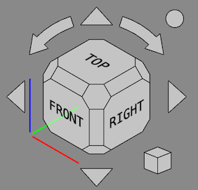
Il Cubo di navigazione è stato aggiornato. Il cubo non viene più mostrato in prospettiva se la Vista 3D è in modalità di visualizzazione ortogonale. Le facce degli angoli sono state rese esagonali e più grandi in modo che siano più facili da cliccare. I bordi sono stati aggiunti intorno ai pulsanti. La selezione e il dimensionamento predefiniti dei caratteri sono stati migliorati. Il menu Mini-cubo ora include una casella di controllo per attivare o disattivare la mobilità del cubo. Sono stati aggiunti diversi nuovi parametri, vedere la pagina Cubo di navigazione per ulteriori informazioni. Pull request #7876, [https ://github.com/FreeCAD/FreeCAD/pull/8266 Pull request n. 8266], Pull request n. 8646 e /FreeCAD/FreeCAD/pull/9356 Pull request #9356. |
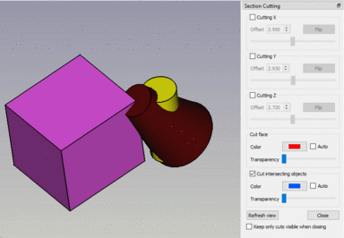 Sezione persistente di oggetti che si intersecano. Fare clic sull'immagine per visualizzare l'animazione. |
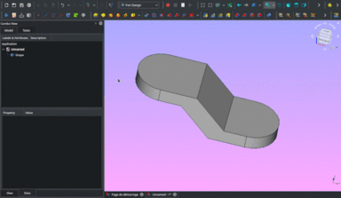
Lo strumento Taglio sezione persistente consente ora di tagliare oggetti che si intersecano. Ciò è utile per gli assiemi in cui a volte non è possibile evitare le intersezioni di oggetti a contatto a causa di problemi numerici. Pull request #8252. |
|
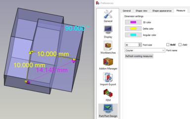
Lo stile di visualizzazione dei risultati misura creati utilizzando l'ambiente Part o PartDesign può ora essere modificato nelle preferenze. |
|
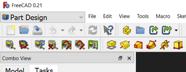
Il selettore dell'ambiente di lavoro può ora essere inserito facoltativamente nella barra dei menu anziché nell'area della barra degli strumenti. |
Ulteriori miglioramenti dell'interfaccia utente
- I pulsanti per
Stampa e
Modalità modifica sono stati rimossi dalla barra degli strumenti File. Possono essere aggiunti di nuovo personalizzando la barra degli strumenti. Pull request n. 7570 e commit ea9a04e
- La barra degli strumenti File è stata divisa. I pulsanti per
Annulla,
Ripristina e
Aggiorna sono stati spostati nella nuova barra degli strumenti Modifica. I pulsanti per
Taglia,
Copia e
Incolla sono stati spostati nella nuova barra degli strumenti degli Appunti. Il pulsante per
Cos'è? è stato spostato nella nuova barra degli strumenti della Guida. Pull request n. 7620
- Sono stati aggiunti comandi a Memorizza e Richiama una vista di lavoro temporanea. Pull request n. 7525
- Le modifiche ai valori con la rotellina del mouse nei "campi di input" (un tipo di widget utilizzato per inserire valori nei pannelli delle attività, ad esempio da Draft Linea) sono disabilitate se il widget non ha il focus e il parametro ComboBoxWheelEventFilter è abilitato. Ciò impedisce modifiche di valore indesiderate durante lo scorrimento, come già accadeva per le caselle rotanti e combinate. Pull request n. 7561
- Ora è possibile impostare una trasparenza predefinita per i nuovi oggetti Part o PartDesign nelle Preferenze. Pull request n. 7103
- C'è il nuovo stile orbita Piatto libero. Può essere abilitato nelle Preferenze o premendo il pulsante
nella Barra di stato e poi utilizzando il menu Impostazioni → Orbita). Pull request n. 8048
- Il pannello attività Impostare l'aspetto degli oggetti ora ha anche un pulsante per impostare la proprietà Point Color. Pull request n. 7708
- È stato aggiunto un pulsante per cambiare i colori del gradiente di sfondo Vista 3D nelle Preferences. Pull request n. 7155
- Tutte le impostazioni di trasparenza utilizzano ora il pulsante di rotazione uniforme del 5%: un clic sul pulsante in una finestra di dialogo o l'editor di proprietà cambia la trasparenza del 5%. Tenere premuto il pulsante per modificare più passi del 5% contemporaneamente. Pull request n. 7723
- La finestra Output è stata rinominata in Report per uniformità con l'interfaccia utente. Pull request n. 7739
- Image Workbench è stato rimosso. Per inserire un piano immagine è ora possibile utilizzare il comando Importa. Fare doppio clic su un piano dell'immagine per modificarne l'orientamento e la scala. Il nuovo comando Carica immagine sostituisce il comando Apri immagine. Pull request n. 8955
- Il deprecato ambiente di lavoro Raytracing è stato rimosso. Al suo posto dovrebbe essere usato Render Workbench esterno. Pull request n. 9420
Sistema principale e API
Sistema principale
- La funzione cbrt(x) per le radici cubiche è stata aggiunta per l'uso in Espressioni. Pull request n. 8629
- Molte nuove Proprietà sono disponibili per lo scripting. Pull request n. 6717
- Aggiunte funzioni di creazione oggetto
vector,matrix,rotation,placementcosì come le funzioni di matricemrotate, { {Incode|mrotatex}},mrotatey,mrotatez,mtranslateper l'uso in Espressioni. Pull request n. 8603.
API
Nuove API Python
- BSplineSurfacePy::scaleKnotsToBounds: Ridimensiona gli elenchi di nodi U e V per adattarli ai limiti specificati. Pull request n. 7258 e Richiesta pull n. 7385
- BSplineCurvePy::scaleKnotsToBounds: Ridimensiona l'elenco dei nodi per adattarlo ai limiti specificati. Pull request n. 7385
- ShapeFix_EdgeConnectPy: classe radice per le operazioni di correzione. commit 4d4adb93
- ShapeFix_EdgePy: correzione del bordo non valido. commit 4089cbfb
- ShapeFix_FaceConnectPy: Ricostruisce la connettività tra le facce nella shell. commit a0eb2e9d
- ShapeFix_FacePy: Classe per correggere le operazioni sulle facce. commit b6cd635c
- ShapeFix_FixSmallFacePy: Classe per operazioni di correzione sulle facce. commit 4c2946c8
- ShapeFix_FixSmallSolidPy: correzione di solidi di piccole dimensioni. commit b70d8d37
- ShapeFix_FreeBoundsPy: Destinato a produrre limiti liberi della forma. commit 1ee1aee1
- ShapeFix_RootPy: classe root per le operazioni di correzione. commit f3e941a3
- ShapeFix_ShapePy: Classe per correggere operazioni sulle forme. commit 87db9dcc
- ShapeFix_ShapeTolerancePy: Modifica le tolleranze delle sotto-forme (vertici, spigoli, facce). commit 125d5b63
- ShapeFix_ShellPy: classe radice per le operazioni di correzione. commit f3e941a3
- ShapeFix_SolidPy: Classe principale per le operazioni di correzione. commit 8d568793
- ShapeFix_SplitCommonVertexPy: Classe per correggere operazioni sulle forme. commit 4b44c54c
- ShapeFix_SplitToolPy: Strumento per dividere e tagliare i bordi. commit bbecc3f2
- ShapeFix_WireframePy: Fornisce metodi per correggere il wireframe della forma. commit 6843a461
- ShapeFix_WirePy: Classe per operazioni di correzione sulle polilinee. commit 94f6279a
- ShapeFix_WireVertexPy: Correzione dei bordi disconnessi nelle polilinee. commit 8c6ffc99
Python API rimosse
- FreeCAD.EndingAdd: sostituito da FreeCAD.addImportType. Pull request n. 7167
- FreeCAD.EndingGet: sostituito da FreeCAD.getImportType. Pull request n. 7167
Addon Manager
Ambiente Arch
- Sono state aggiunte diverse categorie Arch Profilo: IS RHS, IS SHS, IS Angle e IS Tee. Pull request n. 7181 e Pull request n. 7217
- Gli oggetti Arch Profilo ora supportano la modifica del tipo di profilo dopo la creazione. Pull request n. 7217
- Diversi problemi relativi alla modalità di modifica sono stati risolti e i menu contestuali Vista ad albero per gli oggetti Arch sono stati migliorati. Gli oggetti che possono essere modificati ora hanno un'opzione Modifica in quel menu. L'opzione Imposta colori è stata rimossa per gli oggetti senza faccia o che possono avere solo una faccia. Pull request n. 8122
- Gli oggetti Arch Piano di sezione ora gestiscono gli oggetti non solidi allo stesso modo degli oggetti solidi. Pull request n. 8688
Ulteriori miglioramenti Arch
- Lo strumento Inverti posizione cerniera è stato migliorato. Per tutte le polilinee rettangolari ora viene rilevato correttamente il bordo opposto. Pull request n. 8199
- Il Terreno di un Arch Sito ora può anche essere un solido. Pull request n. 8409
- Un Arch Sito non mostra più una rappresentazione fantasma degli oggetti nel suo Gruppo. Pull request n. 8409
Ambiente Draft
- L'imprecisione di Draft Aggancia Vicino durante l'aggancio (snap) alle curve è stata corretta. Inoltre, Draft Aggancia Perpendicolare ora può anche eseguire l'aggancio alle facce e trovare più punti. Per eseguire lo snap a un vertice (ad es. un Draft Punto) Draft Aggancia Punto finale deve ora essere utilizzato invece di Draft Aggancia Vicino. Pull request n. 7132
- Per facilitare il lavoro con i layers, il loro comportamento di trascinamento è stato modificato. Se si rilascia un oggetto da un Gruppo, o un oggetto simile a un gruppo come un Arch Parte di edificio, su un layer, non viene più rimosso dal gruppo e viceversa . Funziona senza tenere premuto il tasto Ctrl. Pull request pull n. 7462
- Il comando Draft Serie su punti ora supporta più tipi di oggetti punto. È possibile utilizzare qualsiasi oggetto con una forma e vertici, nonché una mesh e una nuvola di punti. Pull request n. 7597
- I menu contestuali Vista ad albero per gli oggetti Draft sono stati migliorati. Gli oggetti che possono essere modificati con il comando Draft Modifica, o che hanno una soluzione di modifica dedicata, ora hanno un'opzione Modifica in quel menu. L'opzione Imposta colori è stata rimossa per gli oggetti senza faccia o che possono avere solo una faccia. Pull request n. 7970
- Le proprietà degli oggetti di annotazione di Draft sono state unificate. Gli oggetti Draft Testo, Draft Quota e Draft Etichetta ora hanno tutti una proprietà Nome carattere, Dimensione carattere e Colore testo. Anche le opzioni della modalità di visualizzazione sono state rese coerenti e ora sono: Schermo e Mondo. Issue #7861 e Pull request #8081
- Nel pannello delle attività del comando Draft Imposta stile il pulsante Texts/dims è stato sostituito dal pulsante Annotations. La pressione di questo pulsante elaborerà tutte le annotazioni, incluse Draft Etichette. Sono stati aggiunti i parametri Dim overshoot, Ext lines e Ext overshoot. Sono stati risolti anche diversi problemi aggiuntivi minori. Pull request n. 8190, Pull request n. 8195, .com/FreeCAD/FreeCAD/pull/8196 Pull request #8196 e Pull request #9514.
- Annulla/Ripristina non funzionava correttamente per i comandi di modifica di Draft su Windows. Pull request n. 8267
- Il comando LayerManager è stato migrato dall'ambiente BIM all'ambiente Draft. Pull request n. 8795
Ulteriori miglioramenti di Draft
- Quando si allineava il piano di lavoro con una faccia, veniva ruotato solo per corrispondere agli assi globali se la faccia era un quad. Pull request n. 7249
- Diversi problemi relativi a Draft Serie su tracciato sono stati risolti. Pull request n. 7506 e Pull request n. 7662
- Il comando Draft Modifica ha ricevuto diversi miglioramenti. Per Polilinee, B-spline e Curve di Bézier è stata aggiunta un'opzione Chiudi/Apri al menu contestuale del bordo. Per le B-spline e le curve di Bézier è stata aggiunta allo stesso menu anche l'opzione Inverti. I pannelli delle attività sono stati ripuliti. Pull request n. 7527 e Pull request n. 7541
- L'uso di Esc per uscire da un comando non disattiva più la modalità continua. Pull request n. 7611
- La barra degli strumenti Draft Aggancia è stata modificata in una barra degli strumenti standard. Le scorciatoie da tastiera ora possono essere assegnate agli agganci. Ma usarli durante un comando funziona solo se nessuna delle caselle di input nel pannello delle attività ha il focus mentre "catturano" le cosiddette scorciatoie in comando. Pull request n. 7656
- Diversi bug di Draft Stile delle annotazioni sono stati corretti. Sono stati aggiunti i parametri Colore testo e Spaziatura testo. Pull request n. 8207 e Pull request n. 9702
- Le proprietà Start e End Offset sono state aggiunte agli oggetti Draft Serie su tracciato. Pull request n. 8295
- Una proprietà Count è stata aggiunta alle serie prive di questa proprietà: le versioni non-Link di Draft Serie ortogonale, Draft Serie polare e Draft Serie circolare. Pull request n. 8433
- Il comportamento on/off della griglia è stato corretto. Pull request n. 8818
- La gestione dei convertitori DWG è stata migliorata. Pull requestn. 9444
Ambiente FEM
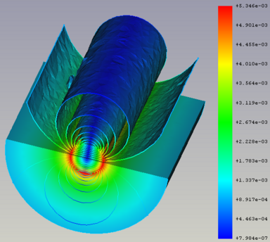 Iso-contorni, raffiguranti la componente y della densità del flusso magnetico assoluto all'interno e intorno a un filo di rame attraversato >corrente elettrica a una frequenza di 100 kHz. Per maggiori informazioni su questo modello, vedere la sezione 14 del Elmer Tutorials . |
C'è il nuovo filtro |
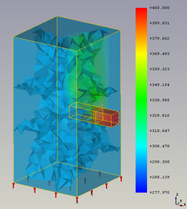 Risultato della simulazione (dell'acqua corrente che viene riscaldata) in cui sono visibili 8 regioni mesh (una per ogni core della CPU utilizzato). |
Ora è possibile eseguire il risolutore Elmer utilizzando più core della CPU. Per maggiori informazioni sugli avvertimenti, vedere questo post del forum |
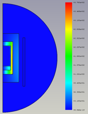 Risultato della simulazione della parte immaginaria della densità di corrente in un crogiolo riscaldato elettricamente da una bobina circostante. Questo modello è disponibile tramite Esempi FEM. Per maggiori informazioni su questo modello, vedere la sezione 16 di Tutorial Elmer. |
La |
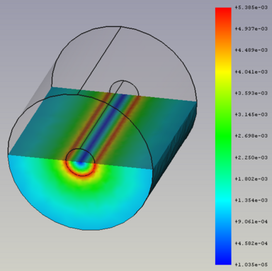 Risultato della simulazione della parte immaginaria della densità del flusso magnetico dentro e attorno a un filo di rame attraversato da corrente elettrica a una frequenza di 100 kHz. Questo modello è disponibile tramite Esempi FEM. Per maggiori informazioni su questo modello, vedere la sezione 14 di funet.fi/index/elmer/doc/ElmerTutorials.pdf Elmer Tutorials. |
La |
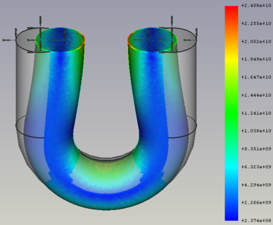 Risultato della simulazione di un filo a U di ferro che viene deformato premendo insieme le estremità della U. Per ulteriori informazioni a riguardo modello, vedere la sezione 8 dei Elmer Tutorials. |
La |
Ulteriori miglioramenti di FEM
- When performing analyses using the
CalculiX solver, there is now also a results pipeline created to visualize the results. Pull request #8525 and Pull request #8903
- It is now possible to perform transient analyses when using the
Elmer solver. Pull request #9056
- The
initial pressure constraint was added to set the initial internal pressure of fluids. Pull request #7364
- The
current density constraint was added to set current densities for bodies and faces. Pull request #8348
- The
magnetization constraint was added to set magnetizations for bodies and faces. Pull request #8393
- The
flow velocity constraint and
initial flow velocity constraint were completely rewritten. It is now also possible to specify a velocity via a math formula (to define a velocity profile). Pull request #8963 and Pull request #8964
Note: This is a breaking change. Analyses with existing flow velocity and initial flow velocity constraints will not work anymore. You have to create new flow velocity constraints in the analysis to make existing analyses work.
Also note: until FreeCAD 0.21 the results of the flow solver were wrong (fluid density and viscosity were a factor 1000 too high). Therefore the necessary recreation of the velocity constraint also assures the results will be correct. - It is now possible to define in the
displacement constraint displacements as equations (displacement according to the current solver time).
- The
body heat source constraint has now a task panel and it is possible to set the heat for several bodies or to use several constraints for different bodies in one analysis. Pull request #7367
- The
spring constraint was not used by any solver. Now it can be used by the Elmer solver via the equations Deformation and Elasticity. Pull request #9005
- The result mesh cut function
Filter function cylinder was added. Pull request #8735
- The result mesh cut function
Filter function box was added. Pull request #8825
- It is now possible to open (and this way visualize) *.pvtu files (partitioned VTK unstructured grid data). A *.pvtu file is also the result of an Elmer simulation, when more than one CPU core is used for calculations. Pull request #7159
- Critical Strain Ratio has been added to the VTK result pipeline. It gives an indication of ductile rupture for materials with a "MaterialMechanicalNonlinear" object. Pull request #7467
FEM mesh to mesh has the new parameter scale to define the scale of deformed mesh using Python. Forum thread and Pull request #7715
- The preferences have a new option to define which solver should automatically be added when creating a new analysis.
- Usability improvements:
- If you are in the FEM workbench when loading a FreeCAD file containing an analysis, the analysis gets activated automatically (you have immediate access to all FEM toolbar buttons).
- The toolbar only has buttons for solvers installed on your system. Unavailable solvers are no longer displayed.
- New example files for the following equations are available via the FEM Examples: Deformation, Flow, Flux, Heat, Magnetodynamic and Magnetodynamic 2D. Pull requests #8550, #8569, #8579, #8597, #8630 and #9004.
- New material card for carbon dioxide and a titanium alloy. Pull request #8332 and Pull request #8636
Esportazione
Mesh
Ulteriori miglioramenti di Mesh
- Supporto per aggiungere trasparenze a una mesh. Thread del forum e Commit f88305e
Ambiente OpenSCAD
Ambiente Part
Ulteriori miglioramenti di Part
- Il comando Part Crea punti da mesh è stato esteso per accettare qualsiasi oggetto geometrico come input. Pull request n. 8730
Ambiente PartDesign
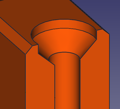 Un controforo. |
La finestra di dialogo Foro supporta il tipo di testa della vite Contropunta. |
|
L'esperienza utente su più finestre di dialogo delle attività di PartDesign per la selezione delle geometrie è stata migliorata, ora non richiede più l'uso di pulsanti separati per aggiungere o rimuovere geometrie alla selezione. Pull request n. 8990 |
Ulteriori miglioramenti di PartDesign
- In the Hole dialog, the deprecated screw head types (cheese head, cap screw etc.) have been removed. They were deprecated since FreeCAD 0.19. Holes using these types are transformed to custom countersinks/counterbore holes with the diameter and depth used by the types. Pull request #7654
- In the Additive Loft and Subtractive Loft dialogs, the previously non-functional option Closed does now create a closed loft (like a ring). Pull request #8748
- The Validate sketch command was added to Helper toolbar. Pull request #7700
- The unusable Leave sketch and View sketch commands were removed from the menu. The Edit sketch, Merge sketches and Mirror sketch commands were added to the menu. Pull request #7700
- The involute gear profile has new properties to change the tooth length. This now allows adjustments for certain types of interferences and to use the profile to create involute splines too. Pull request #8184
- The involute gear profile now offers profile shifting. Issue #5618 and Pull request #8934
- When creating a Clone it will now inherit the colors of the cloned object. Pull request #9547
Ambiente Path
- Camotics integration. If camotics (version 1.2.2 or later) is installed, a new icon will be added to the Path toolbar. Select a Path Job and press the button to open the Camotics dialog. Then drag the slider to generate a simulated solid at any point in the job. You can also launch the full camotics application to run the animated simulaton. This results in a silent post-processing of the job and creation of a camotics project file. Pull request #6637
- Additional substitution strings for automatic output naming. If output is being split into multiple files, the filenames can automatically substitute the toolcontroller label, Work Coordinate Systems (WCS), or operation label. This is in addition to the other existing substitution strings like date, job name, etc.
- Implemented Chipbreaking option for peck style drill cycles. Chipbreaking emits a G73 cycle which causes the control to make a very small retraction move to break the chip without fully retracting the bit from the hole. G73 is supported natively by LinuxCNC. Some other postprocessors will have to interpret the G73 and emit control appropriate codes or decompose the retraction into G1/G0 moves. Postprocessor support for G73 decomposition has been added to the "refactored" postprocessors.Pull request #7469
Modulo Plot
Ambiente Sketcher
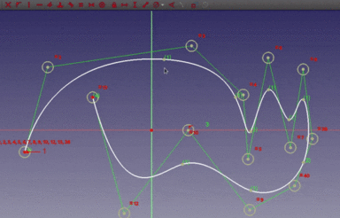 Dragging of B-spline knots. Click on the image to see the animation. |
B-spline knots can now be dragged around and constrained like any other sketch point. |
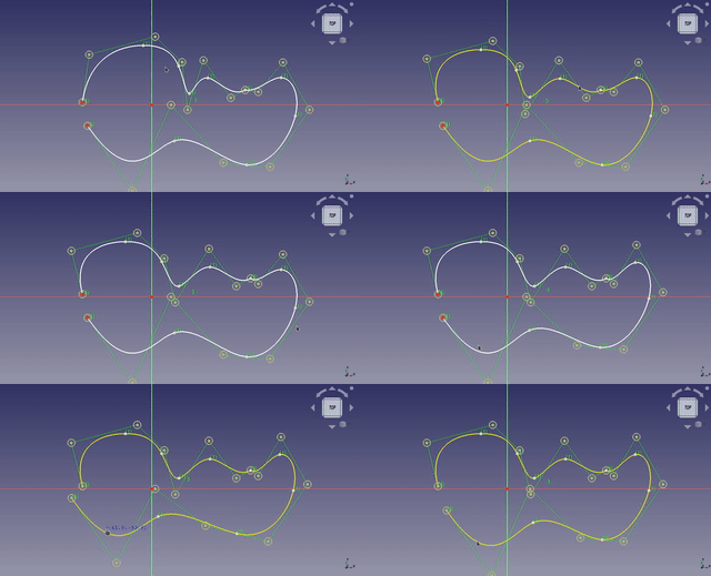 Dragging of a B-spline. Click on the image if the animation does not start. |
Dragging a B-spline now only moves the part between knots. |
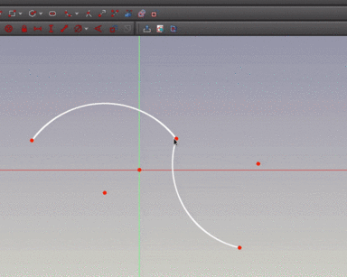 Click on the image to see the animation. |
The Join curves tool has been added. It can combine two curves into a single B-spline. |
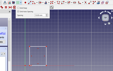
|
The Sketcher grid has been reworked. The Grid tool has been added. Automatic rescalling of grid option has been added. |
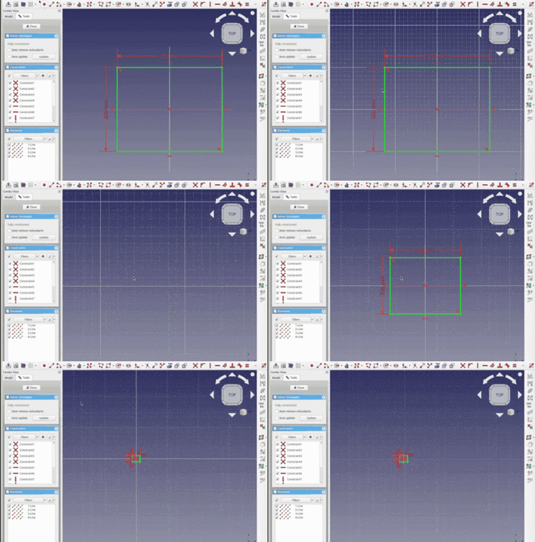
|
A feature to automatically resize the grid according to the zoom level and other improvements were introduced. |
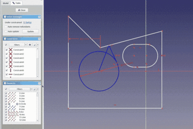
|
Basic visual layers functionality was introduced, for now only 3 hardcoded layers are supported. Expect further improvements down the road.
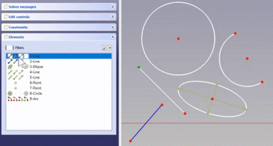
This PR also removes the "Edit controls" widget from the task panel as all it's contents have been moved to other places or removed. The rendering order options have been moved to the Sketcher edit tools toolbar. Pull request #8716 and Pull request #9590 |
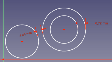
|
Circle to circle distance constraint was introduced. |
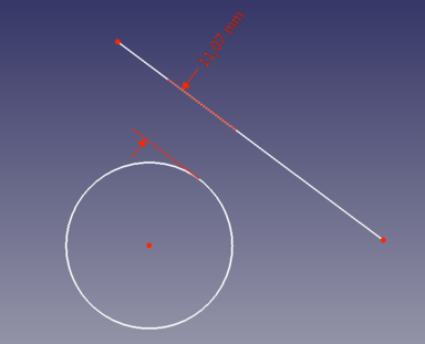
|
Circle to line distance constraint was introduced. |
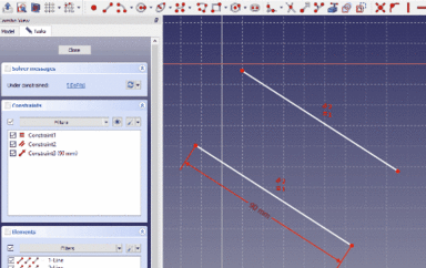 Click on the image to see the animation. |
Snap Manager, snapping at angle and midpoint snap were added. |
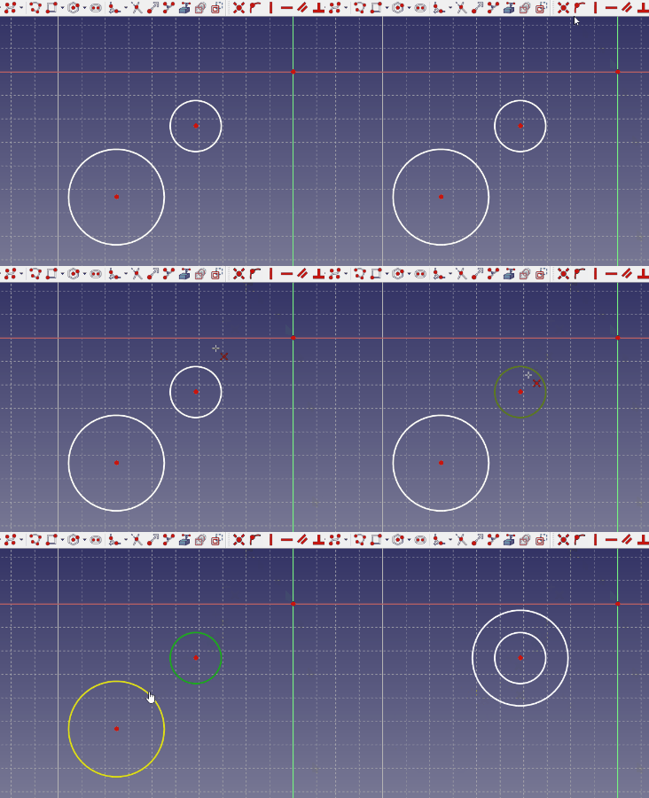
|
Coincident constraint can now act as a concentric constraint when selecting 2 or more circles, arcs, ellipses or arcs of ellipses. |
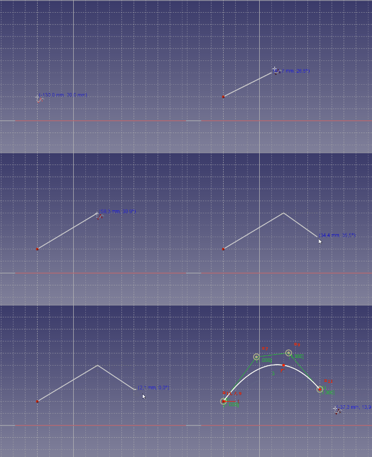
|
B-spline by knots tool was added. |
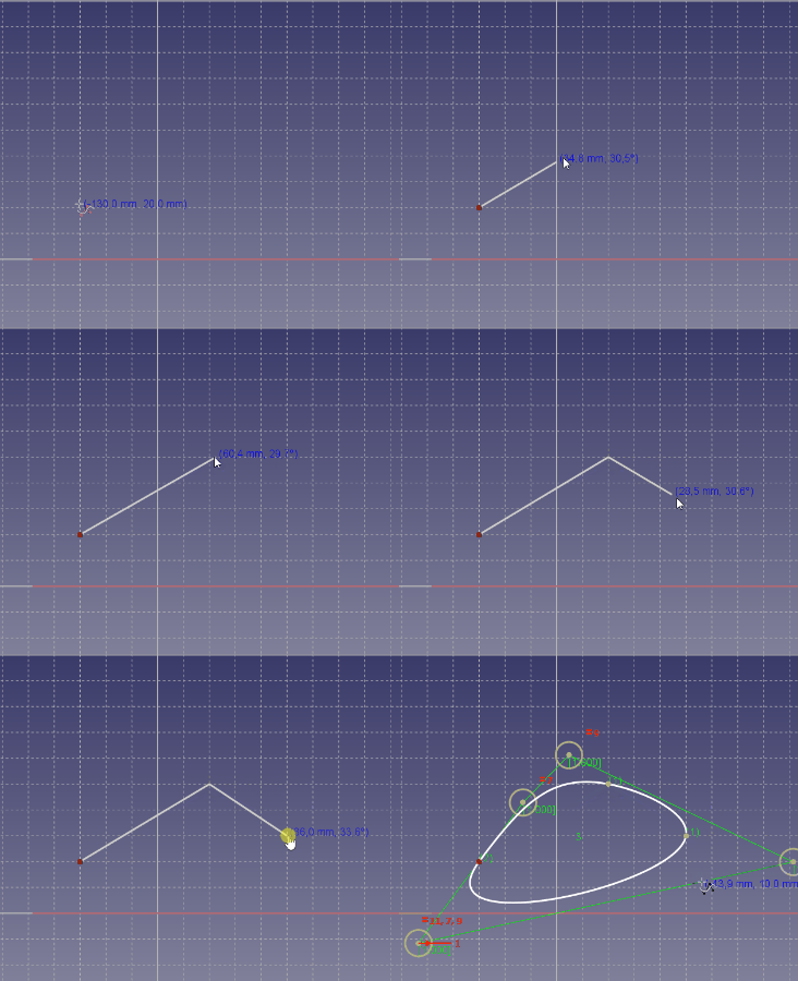
|
Periodic B-spline by knots tool was added. |
Ulteriori miglioramenti di Sketcher
- The toolbar button for Constrain refraction (Snell's law) has been removed. Commit ef62fc3
- Split now supports more curves (ellipses, parabolas, hyperbolas and B-splines). Pull request #6971
- The Dimensional Constraints and Quantity Spin Boxes now support the same math as Expressions (Evaluated in place). Pull Request #7124
- The toolbar buttons for Select redundant constraints and Select conflicting constraints have been removed. Pull request #7568
- The toolbar button for Stop operation has been removed. Pull request #7569
- The toolbar button for Select unconstrained DoF has been removed. Pull request #7603
- The Sketcher toolbar has been split in two: 'Sketcher-edit-mode' and 'Sketcher' (i.e. 'not edit mode'). The Sketcher toolbars that are only for edit-mode are hidden in non-edit-mode, and those only for non-edit-mode are hidden in edit-mode. The Structure toolbar is also hidden in Sketcher. Pull request #7655
- Carbon copy if possible now uses constraint names in the expressions it creates instead of an index based reference, making it more reliable. Pull request #7688
- The Constrain internal alignment tool has been removed. It was obsolete since the introduction of the Show/hide internal geometry tool. Pull request #8863
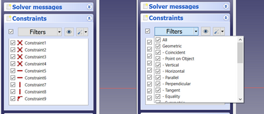
- The Sketcher 'Solver Message' taskbox has been simplified. The auto-remove-redundant checkbox has been moved to the Constraint taskbox setting button menu. The auto-update checkbox has been moved to the menu of the update button. Pull request #8864
Ambiente Spreadsheet
Ulteriori miglioramenti di Spreadsheet
Ambiente Surface
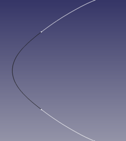
|
The Blend Curve tool was added. |
Ambiente TechDraw
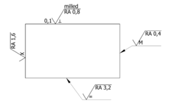
|
The SurfaceFinishSymbol tool was added to allow for the creation of surface finish symbols describing roughness, lay and waviness, but also denoting the type of surface treatment. It supports both ISO and ASME styles. As shown in the image, the existing LeaderLine tool can be used to properly refer oriented symbols to the edges of an object. |
|
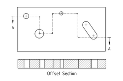
The ComplexSection tool was added to allow for the creation of half, offset and aligned sections. |
|
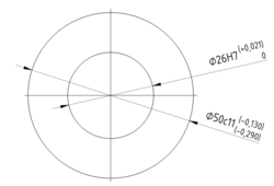
The HoleShaftFit tool was added. |
|
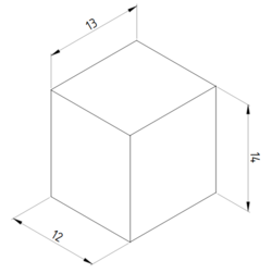
The AxoLengthDimension tool was added. |
Ulteriori miglioramenti di TechDraw
- Navigation modes have been updated to match those used in the 3D view. Pull request #7081 and Pull request #7107
- Bitmap hatching was fixed. Issue #6582 and Pull request #7121
- Support for adjustable gaps for extension lines of dimensions was added. Pull request #7133
- Multithreading was introduced for hidden line removal and face finding. Pull request #7377
- The face detection algorithm was improved. Pull request #7448
- The PrintAll tool was added. Pull request #7460
- Four tools to control the stacking order of views were added. Issue #6012 and Pull request #7460
- ActiveView now creates a screen capture instead of an SVG image. Pull request #7471
- All Latin script templates have been converted to "plain svg". Pull request #7472
- A preview was added to the task panel of the SectionView tool. Pull request #7658
- Deprecated DrawViewPart functions were removed: replaceCenterLine, replaceCosmeticEdge, replaceCosmeticVertex and replaceGeomFormat.
- 3D dimensions can now be created in the same way as 2D dimensions (apart from the fact that the geometry has to be selected in a 3D view). This eliminates the need to link them manually to 3D geometry. Pull request #8141
- The DimensionRepair tool was added. Pull request #8141
- A function to remove overlapping edges returned by the hidden line removal algorithm was added, including a new setting (in advanced preferences) for the number of passes of this function. Pull request #9280
Web
Ambienti esterni
A2plus
Assembly3
Assembly4
FCGear
Ship
Compilazione
Since this release FreeCAD can only be compiled using Qt 5.x and Python 3.x. The lowest supported Qt version is 5.12, the lowest supported Python version is 3.8.
The supported operating systems are:
- Windows 7, 8, 10 and 11
- Linux Ubuntu Focal Fossa (20.04) and newer
- macOS: 10.12 Sierra or newer
Limitazioni note
32bit Windows
Since FreeCAD 0.19 we no longer officially support 32bit Windows. FreeCAD might work on these systems, but no support is given.
Remote Desktop under Windows
Depending on the OpenGL graphics capabilities of a computer, it might be that one encounters a crash when running FreeCAD via remote desktop. To fix this upgrade your OpenGL driver. Only if this doesn't help:
- Download this OpenGL library for 64bit Windows and extract it.
- Rename the DLL file to opengl32sw.dll and copy it to the bin subfolder of FreeCAD's installation folder (overwrite the existing DLL there).
macOS: Start Workbench shows blank page
If the Start Workbench shows only a blank page, you must enable the option Use software OpenGL in the menu FreeCAD-0.21 → Preferences → Display.
