Manual:BIM modeling/pl: Difference between revisions
(Created page with "Teraz musimy połączyć te ściany, aby ładnie się przecinały. Nie jest to konieczne, gdy twoje ściany są narysowane w taki sposób, że już łączą się czysto, ale tutaj musimy to zrobić, ponieważ się przecinają. W środowisku pracy Architektura robimy to wybierając jedną ze ścian, która stanie się "bazą", i dodając do niej inne jako "dodatki". Wszystkie obiekty architektoniczne mogą mieć dowolną liczbę dodatków ''(obiektów, których geometria...") |
(Created page with "* Teraz umieśćmy drzwi. W programie FreeCAD drzwi traktowane są jako szczególny przypadek okien, dlatego wykonuje się to za pomocą narzędzia Okno. * Zacznij od wybrania ściany. Nie jest to konieczne, ale warto przyjąć tę dobrą praktykę. Jeśli obiekt jest zaznaczony podczas uruchamiania narzędzia okna, wymuszisz wstawienie okna w tym obiekcie, nawet jeśli przyciągniesz je do innego obiektu. * Ustaw Draft_SelectPlane/pl|Płaszczyznę r...") |
||
| Line 67: | Line 67: | ||
Poszczególne ściany są jednak nadal dostępne poprzez rozwinięcie ściany w widoku drzewa. |
Poszczególne ściany są jednak nadal dostępne poprzez rozwinięcie ściany w widoku drzewa. |
||
* |
* Teraz umieśćmy drzwi. W programie FreeCAD drzwi traktowane są jako szczególny przypadek okien, dlatego wykonuje się to za pomocą narzędzia [[Arch_Window/pl|Okno]]. |
||
* Zacznij od wybrania ściany. Nie jest to konieczne, ale warto przyjąć tę dobrą praktykę. Jeśli obiekt jest zaznaczony podczas uruchamiania narzędzia okna, wymuszisz wstawienie okna w tym obiekcie, nawet jeśli przyciągniesz je do innego obiektu. |
|||
* Start by selecting the wall. This is not necessary, but a good habit to take. If an object is selected when starting the window tool, you will force the window to be inserted in that object, even if you snap to another object. |
|||
* |
* Ustaw [[Draft_SelectPlane/pl|Płaszczyznę roboczą]] na '''auto''', aby nie ograniczać się do płaszczyzny podłoża. |
||
* |
* Naciśnij przycisk [[Image:Arch_Window.svg|16px]] [[Arch_Window/pl|Okno]]. |
||
* |
* W panelu tworzenia okna wybierz opcję '''Drzwi szklane''', ustaw jego '''Szerokość''' na 0,9 m, a '''Wysokość''' na 2,1 m. |
||
* |
* Upewnij się, że aktywowano funkcję [[Image:Draft_Snap_Near.svg|16px]] [[Draft_Snap_Near/pl|przyciągnij do najbliższego]], abyśmy mogli przyciągać do powierzchni. |
||
* Umieść okno mniej więcej na środku przedniej ściany: |
|||
* Place your window roughly on the middle of the front face of the wall: |
|||
[[Image:Exercise_arch_06.jpg]] |
[[Image:Exercise_arch_06.jpg]] |
||
Revision as of 11:50, 26 February 2024
Ta dokumentacja nie jest ukończona. Prosimy o pomoc w tworzeniu dokumentacji.
Strona Model polecenia GUI wyjaśnia jak powinny być dokumentowane polecenia. Przejrzyj stronę Category:UnfinishedDocu, aby zobaczyć więcej niekompletnych stron, takich jak ta. Zobacz stronę Category:Command Reference aby poznać wszystkie komendy.
Zobacz stronę wytycznych Wikidla FreeCAD aby dowiedzieć się, jak edytować strony Wiki, i przejdź do strony Pomóż w rozwoju FreeCAD, aby dowiedzieć się o innych sposobach, w jakie możesz wnieść swój wkład.
- Słowo wstępne
- Odkrywamy FreeCAD
- Praca z FreeCAD
- Skrypty środowiska Python
- Społeczność
BIM oznacza Modelowanie Informacji o Budynku. Dokładna definicja tego, czym jest BIM, może się różnić, ale możemy po prostu powiedzieć, że jest to sposób modelowania budynków i innych dużych struktur, takich jak mosty, tunele, itp. Modele BIM zwykle oparte są na modelach 3D i obejmują szereg dodatkowych warstw informacji, takich jak informacje o materiałach, relacje do innych obiektów lub modeli, lub specjalne instrukcje dotyczące budowy lub konserwacji. Dodatkowe informacje te umożliwiają różnego rodzaju zaawansowane analizy modelu, takie jak wytrzymałość konstrukcyjna, szacowanie kosztów i czasu budowy, lub obliczenia zużycia energii.
Środowisko pracy Architektura w FreeCAD implementuje szereg narzędzi i udogodnień do modelowania BIM. Chociaż ma on inne cele, został stworzony do współpracy w ścisłej integracji z resztą programu FreeCAD: Cokolwiek zostało wykonane za pomocą dowolnego środowiska pracy w FreeCAD, może stać się obiektem Architektury, lub być wykorzystane jako baza dla obiektu Architektury.
Podobnie jak w środowisku pracy Projekt Części, obiekty generowane przez Środowisko Pracy Architektura są przeznaczone do budowy w rzeczywistości. Dlatego muszą być one „stałe”. Narzędzia Architektury zazwyczaj automatycznie dbają o to, oraz dostarczają narzędzia pomocnicze, które pomagają sprawdzić poprawność obiektów.
Środowisko Pracy Architektura zawiera również wszystkie narzędzia z środowiska pracy Rysunek Roboczy, oraz korzysta z jego siatki i systemu przyciągania. Przed rozpoczęciem pracy zaleca się przejrzenie stron preferencji zarówno w środowisku pracy Rysunek Roboczy, jak i Architektura, i dostosowanie domyślnych ustawień do swoich preferencji.
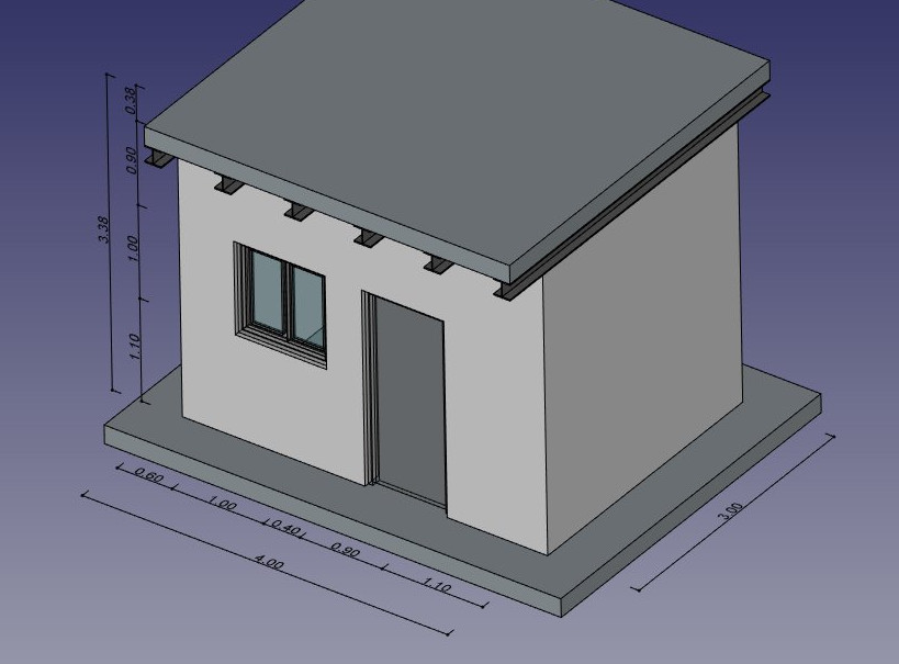
W tym rozdziale zobaczymy, jak modelować ten mały budynek:
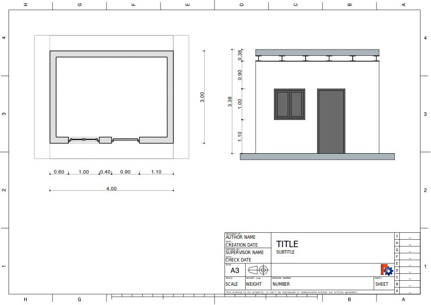
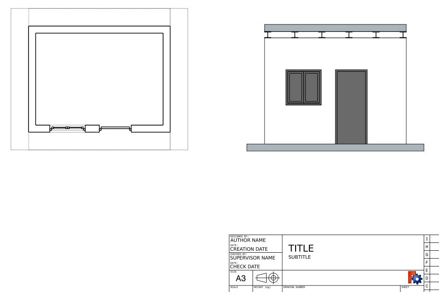
i wygenerować z niego plan i widok przekroju:
- Utwórz nowy dokument i przejdź do środowiska pracy Architektura.
- Otwórz menu Edycja → Preferencje ... → Rysunek Roboczy → Siatka i przyciąganie i ustaw:
- Główne linie co
10. - Odstęp siatki
1000mmaby uzyskać siatkę opartą na metrze, co jest wygodne dla rozmiaru naszej budowli. - Rozmiar siatki
100 linii.
- Główne linie co
- Na pasku narzędzi przyciąganie upewnij się, że przycisk
przyciągnij do siatki jest włączony, aby korzystać z siatki jak najczęściej.
- Jeśli nie widzisz osi, kliknij przycisk
przyciągnij do siatki.
- Ustaw płaszczyznę roboczą na płaszczyznę XY.
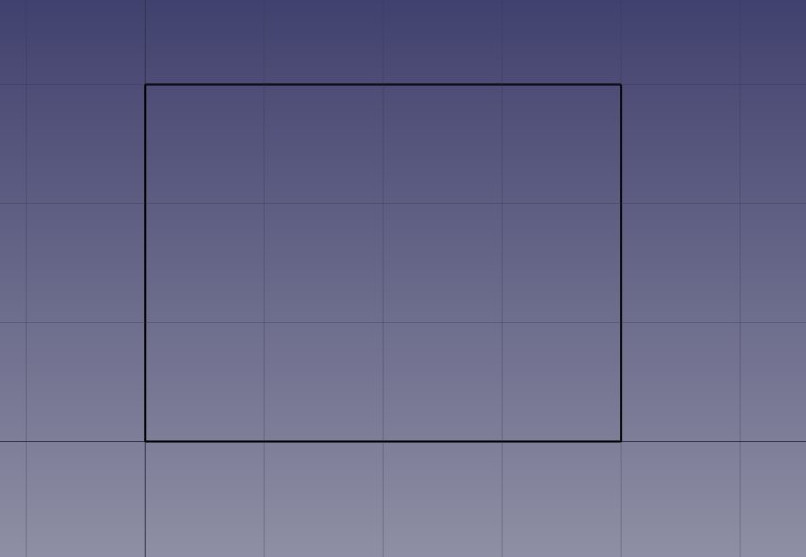
- Oddal widok i przesuń, aby zobaczyć obszar od (0,0) do (4,3). Zobacz stronę nawigacja myszką aby uzyskać szczegółowe instrukcje.
- Narysuj cztery linie za pomocą narzędzia
linia. Możesz wprowadzić współrzędne ręcznie lub po prostu wybrać punkty na siatce za pomocą myszy:
- Od punktu (0,0) do punktu (0,3)
- Od punktu (0,3) do punktu (4,3)
- Od punktu (4,3) do punktu (4,0)
- Od punktu (4,0) do punktu (0,0)
UWAGA: Ze względu na błąd w wersji 0.18, upewnij się, że linie są rysowane w tej kolejności i kierunku.
Zauważ, że zawsze rysowaliśmy w tym samym kierunku (zgodnie z ruchem wskazówek zegara). Nie jest to konieczne, ale zapewni, że wszystkie ściany, które zbudujemy później, będą miały takie same kierunki lewe i prawe. Możesz także pomyśleć, że moglibyśmy po prostu narysować prostokąt, co jest prawdą. Ale cztery linie pozwolą nam lepiej zilustrować, jak dodać jedno obiekt do drugiego.
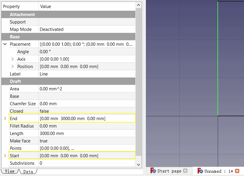
- Po utworzeniu linii sprawdź ich punkty początkowe i końcowe, i dostosuj je w razie potrzeby, aby były dokładnie poprawne.
- Wybierz pierwszą linię, a następnie naciśnij przycisk
Ściana.
- Powtórz tę czynność dla 3 pozostałych linii, aż do uzyskania 4 ścian.
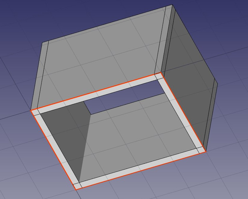
- Wybierz cztery ściany i ustaw ich właściwość Wysokość na 3.00m, a ich właściwość Wyrównanie na w lewo. Jeśli nie narysowałeś linii w tej samej kolejności, co powyżej, niektóre ściany mogą mieć odwrócone kierunki lewy i prawy, i może być konieczne ustawienie ich na prawy. Otrzymasz cztery przecinające się ściany, po wewnętrznej stronie linii bazowych:
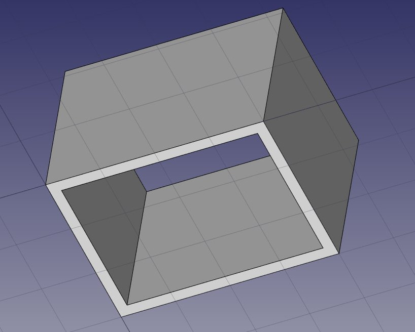
Teraz musimy połączyć te ściany, aby ładnie się przecinały. Nie jest to konieczne, gdy twoje ściany są narysowane w taki sposób, że już łączą się czysto, ale tutaj musimy to zrobić, ponieważ się przecinają. W środowisku pracy Architektura robimy to wybierając jedną ze ścian, która stanie się "bazą", i dodając do niej inne jako "dodatki". Wszystkie obiekty architektoniczne mogą mieć dowolną liczbę dodatków (obiektów, których geometria zostanie dodana do geometrii gospodarza), i ubytków (obiektów, których geometria zostanie odjęta). Dodatki i ubytki obiektu można zarządzać w dowolnym momencie, klikając dwukrotnie obiekt w drzewie.
- Wybierz cztery ściany, trzymając naciśnięty klawisz Ctrl, przy czym ostatnia wybrana będzie ścianą, którą wybierzesz jako bazę.
- Naciśnij przycisk
Dodaj. Cztery ściany zostały teraz połączone w jedną:
Poszczególne ściany są jednak nadal dostępne poprzez rozwinięcie ściany w widoku drzewa.
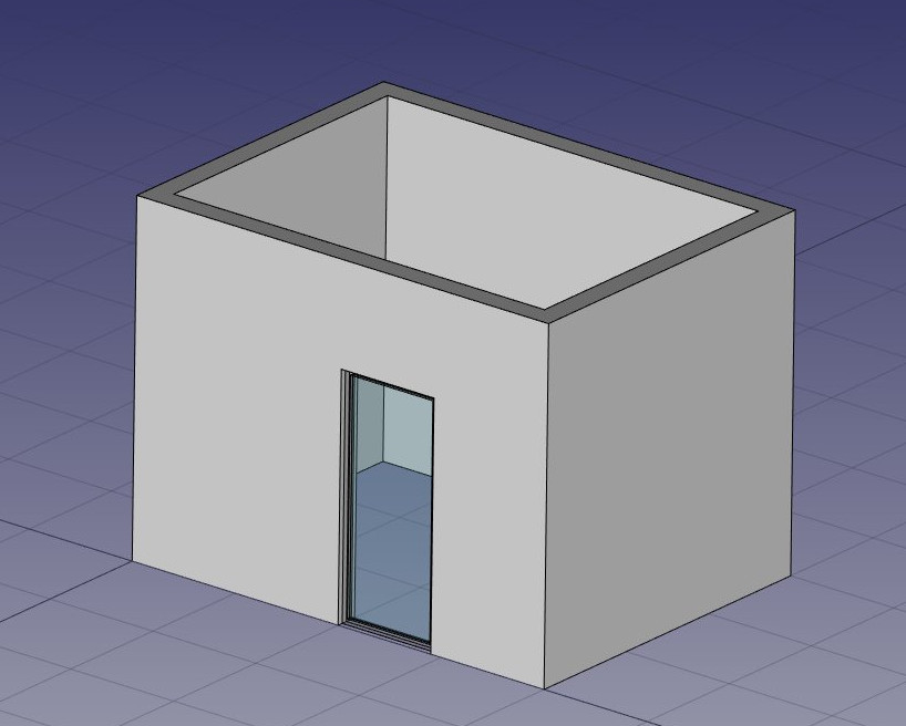
- Teraz umieśćmy drzwi. W programie FreeCAD drzwi traktowane są jako szczególny przypadek okien, dlatego wykonuje się to za pomocą narzędzia Okno.
- Zacznij od wybrania ściany. Nie jest to konieczne, ale warto przyjąć tę dobrą praktykę. Jeśli obiekt jest zaznaczony podczas uruchamiania narzędzia okna, wymuszisz wstawienie okna w tym obiekcie, nawet jeśli przyciągniesz je do innego obiektu.
- Ustaw Płaszczyznę roboczą na auto, aby nie ograniczać się do płaszczyzny podłoża.
- Naciśnij przycisk
Okno.
- W panelu tworzenia okna wybierz opcję Drzwi szklane, ustaw jego Szerokość na 0,9 m, a Wysokość na 2,1 m.
- Upewnij się, że aktywowano funkcję
przyciągnij do najbliższego, abyśmy mogli przyciągać do powierzchni.
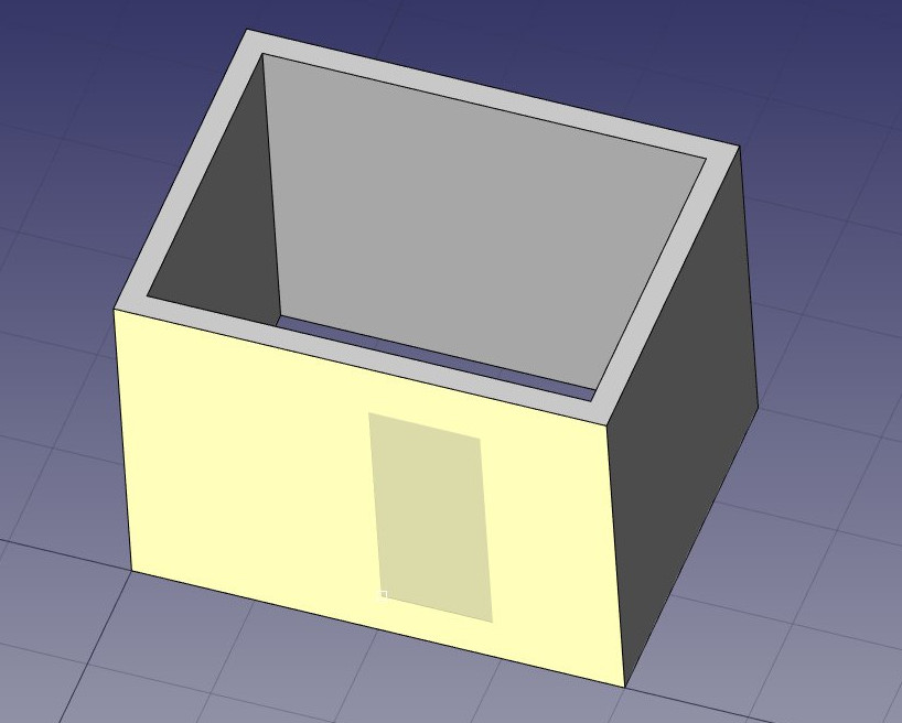
- Umieść okno mniej więcej na środku przedniej ściany:
- Po kliknięciu nasze okno zostanie umieszczone na właściwej powierzchni, ale nie dokładnie tam, gdzie chcemy:
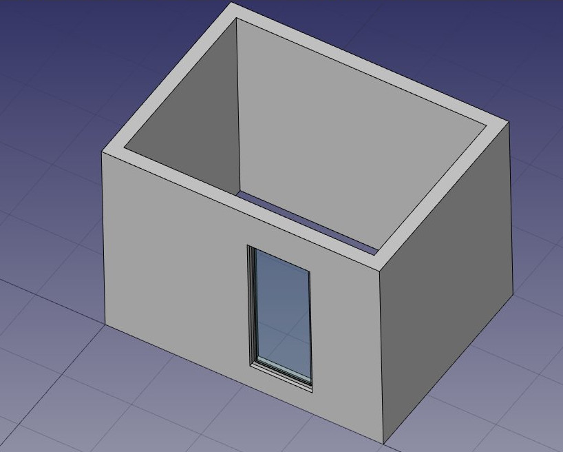
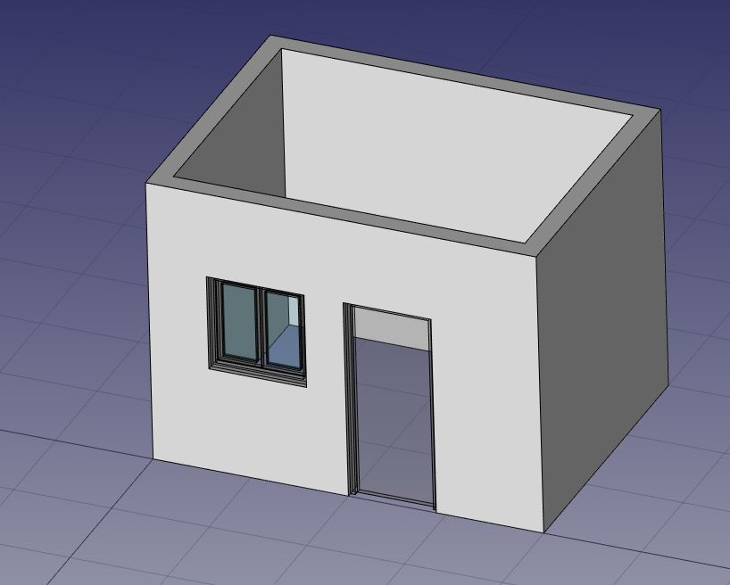
- We can now set the precise location by expanding the wall and the window objects in the tree view, and changing the Placement property of the base sketch of our door. Set its position to x = 2m, y = 0, z = 0. Our window is now exactly where we want it:
- Repeat the operation to place a window: Select the wall, press the window tool, select the Open 2-pane preset, and place a 1m x 1m window in the same face as the door. Set the placement of the underlying sketch to position x = 0.6m, y = 0, z = 1.1m, so the upper line of the window is aligned to the top of the door.
Windows are always built on sketches. It is easy to create custom windows by first creating a sketch on a face, then turning it into a window by selecting it, then pressing the window button. Then, the window creation parameters, that is, which wires of the sketch must be extruded and how much, can be defined by double-clicking the window in the tree view. Now, let's create a slab:
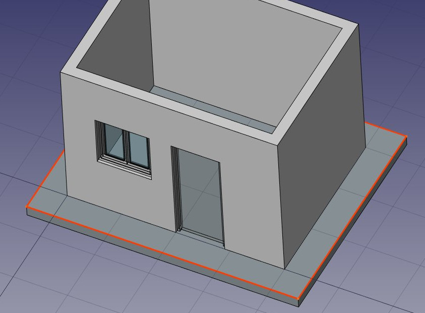
- Set the Working Plane to XY plane
- Create a
rectangle with a length of 5m, a height of 4m, and place it at position x:-0.5m, y:-0.5m, z:0.
- Select the rectangle
- Click the
structure tool to create a slab from the rectangle
- Set the height property of the slab to 0.2m and its normal direction to (0,0,-1) because we want it to extrude downwards. We could also simply have moved it 0.2m down, but it is always good practice to keep extruded objects at the same place as their base profile.
- Set the Ifc Type property of the slab to slab. This is not necessary in FreeCAD, but is important for IFC export, as it will ensure that the object is exported with the correct IFC type.
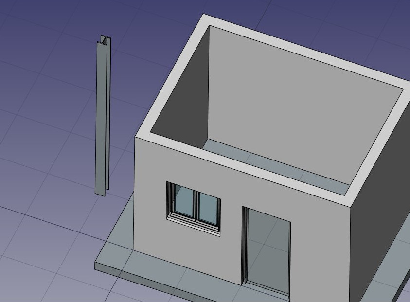
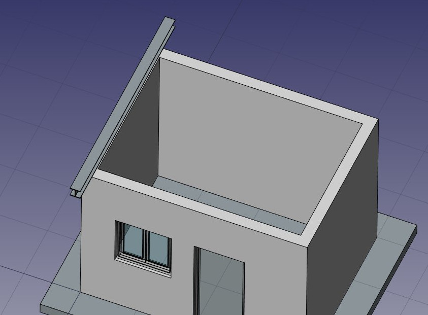
- Let's now use one of the structural presets to make a metallic beam. Click the
structure button, select a HEB 180 preset, and set its height to 4m. Place it anywhere:
- Adjust its placement by setting its Angle to 90° in the (1,0,0) axis, and its position to x:90mm, y:3.5m, z:3.09m. This will position the beam exactly on one of the side walls:
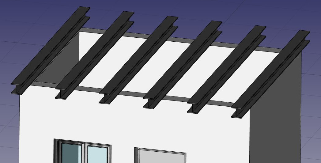
- We need now to duplicate this beam a couple of times. We could do that one by one using the
clone tool, but there is a better way, to do all the copies at once using an array:
- Select the beam
- Press the
Draft OrthoArray button
- Set the Number of elements for the X direction of the array to 6, set the number for the Y and Z direction to 1, and press OK.
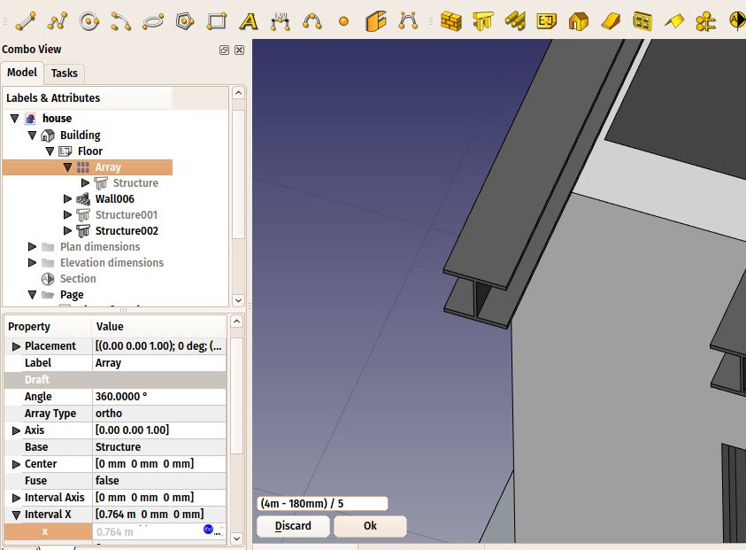
- Expand the interval X property of the array, and press the small
 expression icon at the right side of the X field. This will open an expressions editor:
- Write (4m-180mm)/5 in the expression field, and press OK. This will set the x value to 0.764 (4m is the total length of our front wall, 180mm is the width of the beam, which is why it is called HEB180, and we want a fifth of that space as interval between each beam):
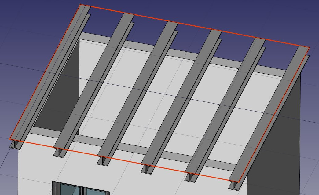
- We can now easily build a simple slab on top of them, by drawing a rectangle directly on the top plane of the beams. Select a top face of one of the beams
- Press the
working plane button. The working plane is now set to that face.
- Create a
rectangle, snapping to two opposite points of the border beams:
- Select the rectangle
- Click the
structure button and create a slab with a height of 0.2m.
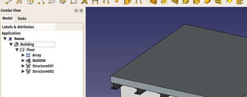
That's it, our model is now complete. We should now organize it so it exports correctly to IFC. The IFC format requires that all objects of a building are inside a building object, and optionally, inside a story. It also requires that all buildings are placed on a site, but the IFC exporter of FreeCAD will add a default site automatically if needed, so we don't need to add one here.
- Select the two slabs, the wall, and the array of beams
- Press the
Floor button
- Select the floor we just created
- Press the
Building button
Our model is now ready to export:
The IFC format is one of the most precious assets in a free BIM world, because it allows the exchange of data between any application and actor of the construction world, in an open manner (the format is open, free and maintained by an independent consortium). Exporting your BIM models as IFC ensures that anyone can see and analyze them, no matter the application used.
In FreeCAD, IFC import and export is done by interfacing with another piece of software, called IfcOpenShell. To be able to export to IFC from FreeCAD, the IfcOpenShell-python package must be installed on your system. Be sure to select one which uses the same python version as FreeCAD. The python version that FreeCAD uses is informed when opening the View -> Panels -> Python console panel in FreeCAD. When that is done, we can now export our model:
- Select the top object you want to export, that is, the Building object.
- Select menu File -> Export -> Industry Foundation Classes and save your file.
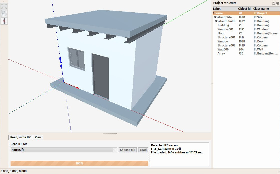
- The resulting IFC file can now be opened in a wide range of applications and viewers (the image below shows the file opened in the free IfcPlusPlus viewer). Checking the exported file in such a viewer application before distributing it to other people is important to check that all the data contained in the file is correct. FreeCAD itself can also be used to re-open the resulting IFC file.
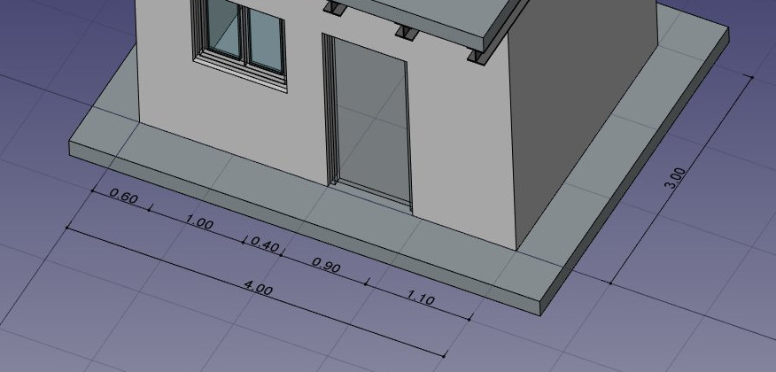
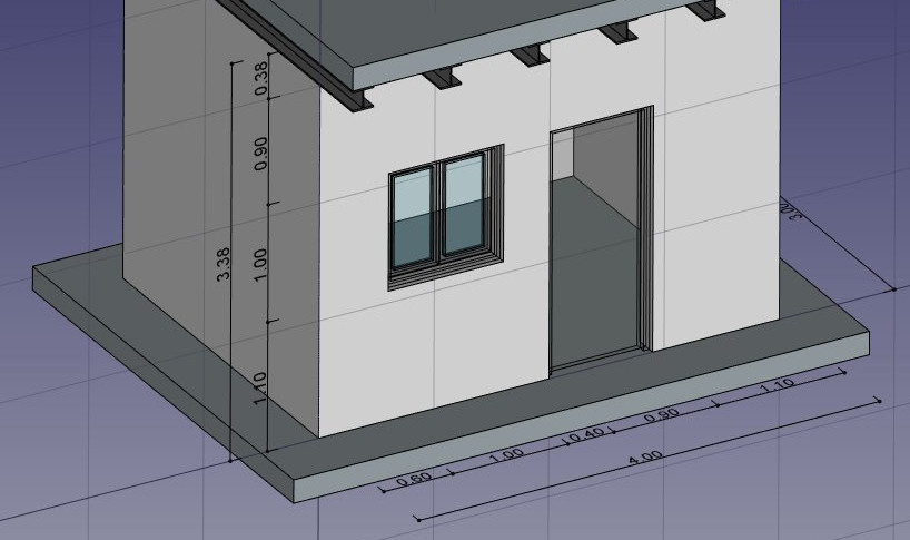
We will now place some dimensions. Unlike the previous chapter, where we drew all the dimensions directly on the Drawing sheet, we will use another method here, and place Draft dimensions directly in the 3D model. These dimensions will then be placed on the Drawing sheet automatically. We will first make two groups for our dimensions, one for the dimensions that will appear in the plan view, and another for those that appear on the elevation.
- Right-click the "house" document in the tree view, and create two new groups: Plan dimensions and Elevation dimensions.
- Set the Working Plane to XY plane
- Make sure the
restrict snap location is turned on, so everything you draw stays on the working plane.
- Draw a couple of
Dimensions, for example as on the image below. Pressing Shift and Ctrl while snapping the dimension points will give you additional options.
- Select all your dimensions, and drag them to the Plan dimensions group in the tree view
- Set the Working Plane to XZ plane, that is, the frontal vertical plane.
- Repeat the operation, draw a couple of dimensions, and place them in the Elevation dimensions group.
We will now prepare a set of views from our model, to be placed on a Drawing page. We can do that with the tools from the Drawing Workbench, as we have seen in the previous chapter, but the Arch Workbench also offers an all-in-one advanced tool to produce plan, section and elevation views, called Section Plane. We will now add two of these section planes, to create a plan view and an elevation view.
- Select the building object in the tree view
- Press the
Section Plane button.
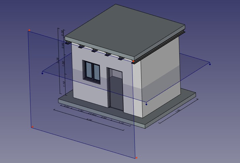
- Set its Display Height property to 5m, its Display Length to 6m, so we encompass our house (this is not needed, but will look better, as it will show naturally what it is used for), and its Placement position at x:2m, y:1.5m, z:1.5m.
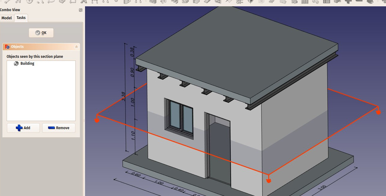
- Check the list of objects considered by the Section Plane by double-clicking it in the tree view. Section Planes only render specified objects from the model, not all of them. The objects considered by the Section Plane can be changed here.
- Repeat the operation to create another section plane, give it the same display length and height, and give it the following Placement: position: x:2m, y:-2m, z:1.5m, angle: 90°, axis: x:1, y:0, z:0. Make sure this new section plane also considers the building object.
- Now we have everything we need, and we can create our Drawing page. Start by switching to the Drawing Workbench, and create a new default
 A3 page (or select another template if you wish).
 - Select the first section plane, used for the plan view
- Press the
 Draft View button. This tool offers a couple of additional features over the standard Drawing View tool, and supports the Section Planes from the Arch Workbench.
 - Give the new view the following properties:
- X: 50
- Y: 140
- Scale: 0.03
- Line width: 0.15
- Show Cut True
- Show Fill: True
- Select the other section plane, and create a new Draft View, with the following properties:
- X: 250
- Y: 150
- Scale: 0.03
- Rendering: Solid
We will now create two more Draft Views, one for each group of dimensions.
- Select the Plan dimensions group
- Press the
 Draft View button.
 - Give the new view the following properties:
- X: 50
- Y: 140
- Scale: 0.03
- Line width: 0.15
- Font size: 10mm
- Repeat the operation for the other group, with the following settings:
- X: 250
- Y: 150
- Scale: 0.03
- Line width: 0.15
- Font size: 10mm
- Direction: 0,-1,0
- Rotation: 90°
Our page is now ready, and we can export it to SVG or DXF formats, or print it. The SVG format allows you to open the file using illustration applications such as Inkscape, with which you can quickly enhance technical drawings and turn them into much nicer presentation drawings. It offers many more possibilities than the DXF format.
Downloads
- The file produced during this exercise: https://github.com/yorikvanhavre/FreeCAD-manual/blob/master/files/house.FCStd
- The IFC file exported from the above file: https://github.com/yorikvanhavre/FreeCAD-manual/blob/master/files/house.ifc
- The SVG file exported from the above file: https://github.com/yorikvanhavre/FreeCAD-manual/blob/master/files/house.svg
Related
- BIM Workbench
- The Arch Workbench
- The Draft working plane
- The Draft snapping settings
- The expressions system
- The IFC format
- IfcOpenShell
- IfcPlusPlus
- Inkscape
- Elementy: Mury, Konstrukcja, ściana kurtynowa, Okna, Drzwi, Dach, Kubatura, Schody, Wyposażenie, Ramy, Ogrodzenie, Kratownica, Profil, Rura, Kształtka
- Zbrojenie: Pręty zbrojeniowe proste, Pręty zbrojeniowe typu U, Pręty zbrojeniowe typu L, Strzemiona, Strzemiona, Pręty zbrojeniowe spiralne, Zbrojenie słupów, Zbrojenie belek, Zbrojenie płyt stropowych, Zbrojenie stóp fundamentowych, Pręt zbrojeniowy
- Panels: Panel, Panelizacja do cięcia, Arkusz panela, Zagnieżdżanie
- Materiał: Wybór materiału, Materiał złożony
- Organizacja: Część budowli, Projekt, Teren, Budowla, Piętro, Odniesienie, Płaszczyzna przekroju, Obmiar
- Osie: Osie, Układ osi, Siatka
- Modifikacja: Płaszczyzna cięcia, Komponent dodaj, Komponent usuń, Przegląd
- Narzędzia: Komponent, Klonuj komponent, Podziel siatkę, Siatka na kształt, Zaznacz siatki nie bryłowe, Usuń kształt., Zamknij otwory, Połącz ściany, Sprawdź, Przełącz flagę Brep IFC, Trzy widoki, Arkusz kalkulacyjny IFC, Przełącz widoczność odjęcia
- Dodatkowe: Preferencje, Ustawienia Importu i Eksportu (IFC, DAE, OBJ, JSON, 3DS); SHP), Architektura: API
