Grundlegendes Sketcher Tutorium
| Thema |
|---|
| Skizzierer |
| Niveau |
| Anfänger |
| Zeit zum Abschluss |
| 60 Minuten |
| Autoren |
| Drei und vocx |
| FreeCAD-Version |
| 0.19 |
| Beispieldateien |
| Grundlegendes Skizzierer Tutorium aktualisiert |
| Siehe auch |
| None |
Einführung
Dieses Tutorium wurde ursprünglich von Drei geschrieben, und es wurde von vocx neu geschrieben und illustriert.
Dieses Tutorium soll den Leser in den grundlegenden Arbeitsablauf des Skizzierer Arbeitsbereich einführen.
Der Skizzierer Arbeitsbereich existiert als eigenständiges Modul, so dass es zum Zeichnen von generischen 2D (planaren) Objekten verwendet werden kann. Es wird jedoch meistens in Verbindung mit dem PartDesign Arbeitsbereich verwendet. Eine geschlossene Skizze wird normalerweise verwendet, um eine Fläche oder ein Profil zu erzeugen, die bzw. das mit einer Anwendung wie
PartDesign Polster in einen Volumenkörper extrudiert wird.
Der Leser wird üben:
- Konstruktionsgeometrie erstellen
- Reale Geometrie erzeugen
- Anwenden von geometrischen Beschränkungen
- Anwenden von Bezugspunktbeschränkungen
- Erhalten eines geschlossenen Profils
Für eine genauere Beschreibung des Skizzierers, lese die Skizzierer Referenz.
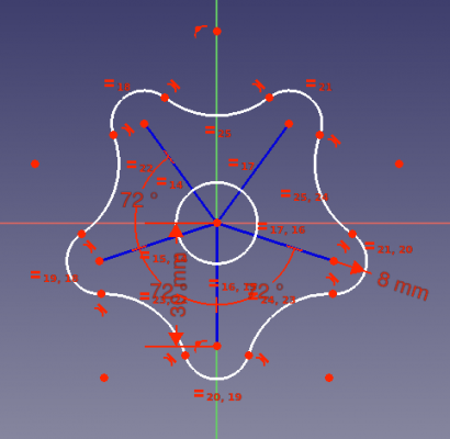
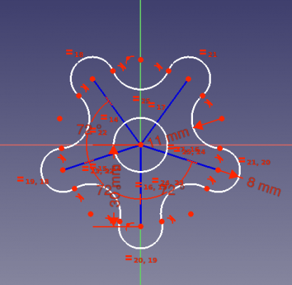
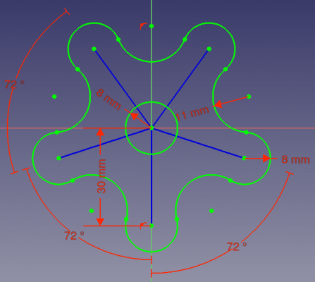
Endergebnis der Skizze, wobei die gesamte Geometrie vollständig beschränkt ist, einschließlich der Konstruktionsgeometrie zur Unterstützung.
Einrichtung
1. Öffne FreeCAD, erstelle ein neues leeres Dokument mit Datei → Neu.
- 1.1. Wechsle zum Skizzierer Arbeitsbereich über den Arbeitsbereich Wähler oder das Menü Ansicht → Arbeitsbereich → Skizzierer.
Einige Aktivitäten zum Erinnern:
- Drücke die rechte Maustaste, oder drücke Esc einmal auf der Tastatur, um das aktive Werkzeug im Bearbeitungsmodus abzuwählen.
- Um den Skizzenbearbeitungsmodus zu verlassen, drücke die Schließen Schaltfläche im Aufgabenpaneel oder drücke Esc zweimal auf der Tastatur.
- Um den Bearbeitungsmodus erneut aufzurufen, doppelklicke auf die Skizze in der Baumansicht oder wähle sie aus und klicke dann auf
Skizze bearbeiten.
Erstellen einer Skizze
2. Klicke auf Neue Skizze.
- 2.1. Wähle die Skizzenausrichtung, d.h. eine der Basisebenen XY, XZ oder YZ. Wähle auch, ob du eine umgekehrte Ausrichtung und einen Versatz von der Grundebene wünschst.
- 2.2. Wir werden die Standardebene und -optionen verwenden.
- 2.3. Klicke auf OK , um mit der Konstruktion der Skizze zu beginnen.
Wir befinden uns jetzt im Skizzenbearbeitungsmodus. Innerhalb dieses Modus können wir die meisten Werkzeuge dieses Arbeitsbereichs nutzen.
Hinweis: Die Baumansicht wechselt zum Aufgabenpaneel; in dieser Oberfläche erweitere den Bedienelemente bearbeiten Abschnitt und stelle sicher, dass die Auto Beschränkungen Option aktiviert ist. Andere Optionen können geändert werden, einschließlich der Größe des sichtbaren Gitters und der Frage, ob wir am Gitter einrasten wollen; in diesem Tutorium werden wir nicht am Gitter einrasten und wir werden es auch ausblenden. In anderen Abschnitten des Aufgabenpaneel kannst du auch sehen, welche geometrischen Elemente und Beschränkungen definiert wurden.
Oberer Teil des Aufgabenpaneel des Skizzierers.
Konstruktionsgeometrie
3. Die Konstruktionsgeometrie wird verwendet, um die Erstellung von "echter" Geometrie zu leiten. Die reale Geometrie wird außerhalb des Bearbeitungsmodus der Skizze angezeigt, während die Konstruktionsgeometrie nur innerhalb des Bearbeitungsmodus angezeigt wird. Daher kannst du so viel Konstruktionsgeometrie verwenden, wie du zum Erstellen von realen Formen benötigst.
- 3.1. Klicke auf
Konstruktion umschalten. Jetzt werden geometrische Elemente im Konstruktionsmodus gezeichnet.
- 3.2. Klicke auf
Linie Erstellen.
- 3.3. Nähere dich dem Ursprung der Skizze, der Punkt sollte aufleuchten und in der Nähe deines Mauszeigers das
Deckungsgleiche Beschränkung Symbol erscheinen.
- 3.4. Klicke auf den Punkt und bewege dann den Zeiger, um eine neue Linie von diesem Punkt aus zu zeichnen. Bewege den Zeiger so, dass die Linie eine Länge von etwa
30 mmhat. Du musst in diesem Schritt nicht sehr genau sein; später werden wir die korrekte Abmessung einstellen. - 3.5. Wiederhole diesen Vorgang vier weitere Male, um Konstruktionslinien in einem Sternenmuster zu platzieren. Kümmere dich nicht allzu sehr um ihre Größe oder Position, verlängere sie einfach in den vier Quadranten.
- 3.6. Verlasse jetzt den Konstruktionsmodus, durch erneutes klicken auf
Konstruktion umschalten.
Hinweis: bis zu diesem Punkt ist das Linienwerkzeug noch aktiv. Das bedeutet, dass wir weiterhin auf die 3D Ansicht klicken können, um so viele Linien zu zeichnen, wie wir wollen. Wenn wir dieses Werkzeug verlassen möchten, können wir die rechte Maustaste drücken oder Esc auf der Tastatur einmal drücken. Auf diese Weise erzeugt der Zeiger keine Linien mehr, sondern ist nur noch ein Zeiger, mit dem wir die gerade erzeugten Objekte auswählen können. In diesem Zeigermodus können wir die Endpunkte jeder Linie auswählen und ziehen, um ihre Platzierung anzupassen.
Note 2: do not press Esc a second time as this will exit the sketch edit mode. If you do this, re-enter the edit mode by double clicking on the sketch in the tree view.
Take a look at the task panel again. The Solver messages section already indicates that the sketch is under-constrained, and it mentions the number of degrees of freedom.
Look at the Constraints and Elements sections to see the new listed constraints and lines. Once your sketches have many elements, it may be difficult to select them in the 3D view, so you can use these lists to select the object that you wish exactly.
Konstruktionslinien, die eine Sternform mit dem Zentrum im Ursprung bilden.
Reale Geometrie
.
Make sure you are not in construction mode by clicking on Toggle construction, if you have not previously exited this mode.
Äußere Bögen
4. Create a circle.
- 4.1. Click on
Create circle.
- 4.2. Click on the origin of the sketch to position its center point.
- 4.3. Click anywhere in the 3D view to set the circumference radius as a distance from the origin. Make it approximately
8 mm. Again the dimension will be fixed later.
5. Create a series of arcs.
- 5.1. Click on
Create arc.
- 5.2. Approach the endpoint of one of the construction lines, and click on it. This will set the center point of the circular arc to be
coincident with this line's endpoint.
- 5.3. Click once in the 3D view at an arbitrary location to set simultaneously the radius of the arc, and the first endpoint of it. Define an approximate radius of
8 mm. - 5.4. Move the pointer in an anti-clockwise direction to trace an arc that has its concavity pointing towards the origin of the sketch. Click to set the final endpoint of the arc, defining a circular arc that approximately sweeps
180°or half a circle. - 5.5. Repeat these steps with each construction line, so that each of them has a circular arc at its tip. We will call these O-arcs for outwards-arcs.
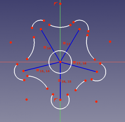
Circular arcs added at the endpoints of the construction lines. Also a central circle.
Innere Bögen
6.
To summarize, the O-arcs should have their curvature pointing outwards, and their concavity pointing towards the origin of the sketch; the I-arcs should have their curvature pointing inwards, and their concavity pointing away from the same origin.
Circular arcs added between the first set of arcs placed.
Beschränkungen
Take a look at the task panel again. Due to the new geometrical elements that we have drawn, the Solver messages section indicates even more degrees of freedom. A degree of freedom (DOF) indicates a possible movement of one element. For example, a point can be moved both in horizontal and vertical directions, so it has two degrees of freedom. A line is defined by two points, therefore in total it has four degrees of freedom. If we fix one of those points, then the entire system has only two degrees of freedom available; if we additionally fix the horizontal movement of the remaining point, we only have one degree of freedom left; and if we also fix the vertical movement of this point, then the last degree of freedom disappears, and the line cannot move from its position any more.
.
There are two principal types of constraints:
- Geometric constraints define characteristics of the shapes without specifying exact dimensions, for example, horizontality, verticality, parallelism, perpendicularity, and tangency.
- Datum constraints define characteristics of the shapes by specifying dimensions, for example, a numeric length or an angle.
Geometrische Beschränkungen
Gleiche Länge und gleicher Radius
.
- 7.3. Select all five O-arcs, those centered on an endpoint of a construction line.
- 7.4. Press
Equal length.
- 7.5. Repeat with all I-arcs, those between the O-arcs.
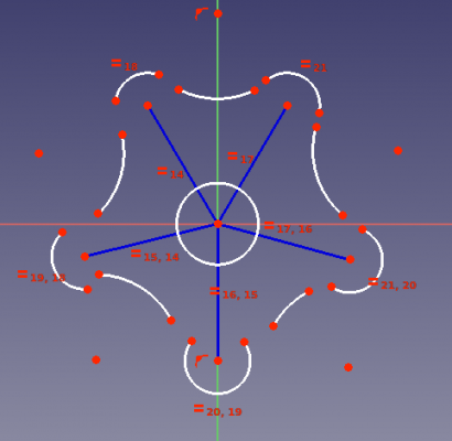
- Note: again the constraints are chained. Therefore all O-arcs will have the same radius, and all I-arcs will have the same radius. At this moment, the specific value of these lengths is not fixed. You may use the pointer to drag a point and see how the sketch is updated while respecting the constraints in place.
.
Note: as you add constraints, overlay symbols indicating the type of constraint appear over the geometry in the 3D view. If these symbols obfuscate your view, you can hide them by unchecking the constraint in the task panel. Also note that the number of degrees of freedom decreases after adding each constraint.
Note 2: if you wish to temporarily disable the constraint, you may select it and press Toggle active constraint. When you want to apply it again, press again the same button.
Sketch with equality constraints applied to the construction lines, and to the two sets of arcs.
Tangentialität
.
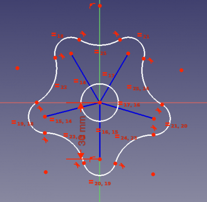
Note: applying the tangential constraint very often will move the geometry around in order to produce a smooth connection. You may have to use the pointer to reposition the points a bit before applying the next tangential constraint. Try placing the endpoints in such a way that two arcs aren't too far apart, so they can be connected with a short line rather than a long line.
.
Sketch with tangential constraints applied to the arcs, which closes the shape.
Bezugspunktbeschränkungen
These constraints specify the numerical distances between two points, and angles between two lines.
Abstände und Winkel
.
.
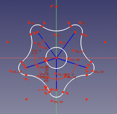
Sketch with length constraint applied to one vertical construction line (left), and angle constraints to three pairs of construction lines (right).
Radius
.
Sketch with radius constraints applied to the outwards arcs (left), and inwards arcs (right).
- 11.7. Finally, select the circle in the center of the sketch, press
Radius, and set the value to
8 mm.
.
Sketch with all geometrical and datum constraints applied.
Extrusion
12. Now that we have a fully constrained sketch, it can be used to create a solid body.
- 12.1. Exit the sketch edit mode by pressing the Close button, or pressing Esc twice. The sketch should appear in the tree view and the 3D view.
- 12.2. Switch to the PartDesign Workbench.
- 12.3. With the sketch selected in the tree view, press
PartDesign Body, choose the default XY-plane, and press OK. The sketch should appear now inside the Body.
- 12.4. Select the sketch, and then press
PartDesign Pad, choose the default options, and press OK to create a solid extrusion.
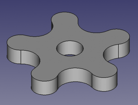
Left: fully constrained sketch with only the most important constraints showing. Right: solid extrusion produced with PartDesign Pad.
Zusätzliche Informationen
For a more in depth description of the sketcher, visit the Sketcher Workbench documentation and also read the Sketcher reference.
Constraining a sketch can be done in many different ways. In general, it is recommended to use geometrical constraints first, and minimize the number of datum constraints, as this simplifies the task of the internal constraint solver. To investigate this, repeat this example, now adding the constraints in different order.
- First constrain the construction lines before drawing the arcs.
- Or constrain the size of the arcs before making them tangent.
- Or set the angle of the construction lines before adding more elements.
- Try using other construction geometry.
(FIXME)
- Die Werkzeuge: Skizze erstellen, Skizze bearbeiten, Skizze verlassen, Skizze anzeigen, View section, Skizze einer Fläche zuordnen..., Reorient sketch, Skizze überprüfen, Skizzen zusammenführen, Skizze spiegeln
- Skizzen-Geometrien: Punkt, Linie, Bögen erstellen, Bogen, Kreisbogen durch drei Punkte, Kreise erstellen, Kreis, Kreis durch drei Punkte, Kegelförmige Körper erstellen, Ellipse mit Mittelpunkt, Ellipse durch drei Punkte, Ellipsenbogen, Hyperbel erstellen, Parabel erstellen, B-splines erstellen, B-spline, Create periodic B-spline, Linienzug (Mehrpunktlinie), Rechteck, Reguläres Polygon erstellen, Dreieck, Quadrat, Fünfeck, Sechseck, Siebeneck, Achteck, Create Regular Polygon, Nut, Abrundung erstellen, Kante zuschneiden, Verlängern, Externe Geometrie, CarbonCopy, Konstruktionsmodus
- Skizzenbeschränkungen
- Geometrische Beschränkungen Koinzidenz erzwingen, Punkt auf Objekt festlegen, Vertikal, Horizontal, Parallel, Orthogonal, Tangente, Gleichheit, Symmetrisch, Constrain Block
- Dimensional constraints Sperren, Horizontaler Abstand, Vertikaler Abstand, Distanz festlegen, Radius festlegen, Winkel festlegen, Snell's Law, Umschalten auf steuernde Bemaßung,
- Sketcher tools Select solver DOFs, Close Shape, Connect Edges, Select Constraints, Select Origin, Select Vertical Axis, Select Horizontal Axis, Select Redundant Constraints, Select Conflicting Constraints, Select Elements Associated with constraints, Show/Hide internal geometry, Symmetry, Clone, Copy, Move, Rectangular Array, Delete All Geometry, Delete All Constraints
- Sketcher B-spline tools Show/Hide B-spline degree, Show/Hide B-spline control polygon, Show/Hide B-spline curvature comb, Show/Hide B-spline knot multiplicity, Convert Geometry to B-spline, Increase degree, Increase knot multiplicity, Decrease knot multiplicity
- Sketcher virtual space Switch Virtual Space
- Erste Schritte
- Installation: Herunterladen, Windows, Linux, Mac, Zusätzlicher Komponenten, Docker, AppImage, Ubuntu Snap
- Grundlagen: Über FreeCAD, Graphische Oberfläche, Mausbedienung, Auswahlmethoden, Objektname, Programmeinstellungen, Arbeitsbereiche, Dokumentstruktur, Objekteigenschaften, Hilf FreeCAD, Spende
- Hilfe: Tutorien, Video Tutorien
- Arbeitsbereiche: Std Base, Arch, Assembly, CAM, Draft, FEM, Inspection, Mesh, OpenSCAD, Part, PartDesign, Points, Reverse Engineering, Robot, Sketcher, Spreadsheet, Start, Surface, TechDraw, Test Framework, Web


