PartDesign Draft/de: Difference between revisions
(Updating to match new version of source page) |
(Updating to match new version of source page) |
||
| Line 65: | Line 65: | ||
==Optionen== |
==Optionen== |
||
| ⚫ | |||
* {{MenuCommand|Add face}}: Add faces to the selection by pressing the {{Button|Add face}} button and selecting more faces. |
* {{MenuCommand|Add face}}: Add faces to the selection by pressing the {{Button|Add face}} button and selecting more faces. |
||
* {{MenuCommand|Remove face}}: Choose a way to remove faces from the selection: |
* {{MenuCommand|Remove face}}: Choose a way to remove faces from the selection: |
||
** Select one or more faces in the list and press the {{KEY|Del}} key or right-click the list and select {{MenuCommand|Remove}} from the context menu. |
** Select one or more faces in the list and press the {{KEY|Del}} key or right-click the list and select {{MenuCommand|Remove}} from the context menu. |
||
** Press the {{Button|Remove face}} button. All previously selected faces are highlighted in purple. Select each face to be removed. |
** Press the {{Button|Remove face}} button. All previously selected faces are highlighted in purple. Select each face to be removed. |
||
| ⚫ | |||
* {{MenuCommand|Neutral plane}}: Set the the neutral plane by pressing the {{Button|Neutral plane}} button and selecting the plane that must not change dimensionally. |
* {{MenuCommand|Neutral plane}}: Set the the neutral plane by pressing the {{Button|Neutral plane}} button and selecting the plane that must not change dimensionally. |
||
* {{MenuCommand|Pull direction}}: Set the the pull direction by pressing the {{Button|Pull direction}} button, then select an edge. Pull Direction is only effective if the Neutral Plane has been set. Results can be unpredictable. |
* {{MenuCommand|Pull direction}}: Set the the pull direction by pressing the {{Button|Pull direction}} button, then select an edge. Pull Direction is only effective if the Neutral Plane has been set. Results can be unpredictable. |
||
Revision as of 17:29, 6 June 2022
|
|
| Menüeintrag |
|---|
| Part Design → Modifikationen → Formschräge |
| Arbeitsbereich |
| Part Design |
| Standardtastenkürzel |
| - |
| Eingeführt in Version |
| - |
| Siehe auch |
| Keine |
Beschreibung
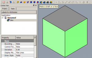
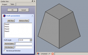
Das Werkzeug PartDesign Formschräge versieht die ausgewähleten Flächen eines Objekts mit einer (Entform-)Schräge. Es fügt dem Dokument ein Draft-Objekt und den dazugehörigen Repräsentanten in der Baumansicht hinzu.
Anwendung
Eine Formschräge hinzufügen
- Falls nötig, wird der abzuschrägende Körper aktiviert.
- Eine oder mehrere Flächen des Körpers auswählen.
- Es gibt mehrere Möglichkeiten das Werkzeug aufzurufen:
- Die Schaltfläche
Formschräge drücken.
- Den Menüeintrag Part Design → Modifikationen →
Formschräge auswählen.
- Die Schaltfläche
- Wenn kein Körper aktiv ist und sich zwei oder mehr Körper im Dokument befinden, offnet sich der Dialog Active Body Required und fordert zur Aktivierung eines Körpers auf. Ist nur ein einziger Körper vorhanden, wird er automatisch ausgewählt.
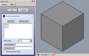
- Der Aufgabenbereich Parameter der Formschräge wird geöffnet. Siehe Optionen für weitere Informationen.
- Zum Fertigstellen die OK-Schaltfläche drücken.
- Nicht vergessen:
- Da das Werkzeug immer mindestens eine Fläche erfordert, kann die letzte vorhandene Fläche nicht aus der Liste entfernt werden.
Eine Formschräge bearbeiten
- Eine der folgenden Möglichkeiten startet die Bearbeitung:
- Das Draft-Objekt in der Baumansicht doppelt anklicken.
- Das Draft-Objekt in der Baumansicht mit der rechten Maustaste anklicken und Draft bearbeiten aus dem Kontextmenü auswählen.
- Der Aufgabenbereich Parameter der Formschräge wird geöffnet. Siehe Optionen für weitere Informationen.
- Zum Fertigstellen die OK-Schaltfläche drücken.
Optionen
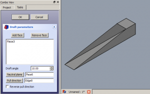
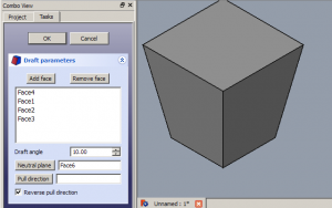
- Add face: Add faces to the selection by pressing the Add face button and selecting more faces.
- Remove face: Choose a way to remove faces from the selection:
- Select one or more faces in the list and press the Del key or right-click the list and select Remove from the context menu.
- Press the Remove face button. All previously selected faces are highlighted in purple. Select each face to be removed.
- Draft angle: Set the Draft angle either by entering a value or by clicking the up/down arrows.
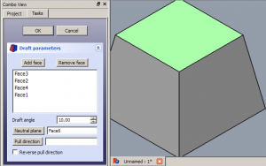
- Neutral plane: Set the the neutral plane by pressing the Neutral plane button and selecting the plane that must not change dimensionally.
- Pull direction: Set the the pull direction by pressing the Pull direction button, then select an edge. Pull Direction is only effective if the Neutral Plane has been set. Results can be unpredictable.
- Reverse pull direction: Invert the pull direction by checking the Reverse pull direction checkbox. This will toggle the draft between positive and negative angles.
Hinweise
- Das Werkzeug Formschräge arbeitet nur mit Flächen, die nicht tangential mit anderen Flächen verbunden sind. (Hier sollte das englische Original präzisiert werden...) A common mistake is to attempt to apply draft to a face that already has a fillet applied to it. To solve this, remove the fillet, apply the draft as needed, then re-apply the fillet.
Eigenschaften
Siehe auch: Eigenschafteneditor.
Ein PartDesign-Draft-Objekt wird von einem Part-Formelement abgeleitet und erbt alle seine Eigenschaften. Außerdem hat es die folgenden zusätzlichen Eigenschaften:
Daten
Basis
- Daten-EigenschaftAngle (
Angle): Kann nicht negativ sein. Standardwert:1,5 °. - Daten-EigenschaftReversed (
Bool): Standardwert:false. - Daten-EigenschaftBase (
LinkSub): Sub-link to the parent feature's list of selected edges and faces. - Daten-EigenschaftSupport Transform (
Bool): "Include the base additive/subtractive shape when used in pattern features. If disabled, only the dressed part of the shape is used for patterning". Standardwert:false. - Daten-Eigenschaft (versteckt)Add Sub Shape (
PartShape) - Daten-Eigenschaft (versteckt)Base Feature (
Link): Link to the parent feature. - Daten-Eigenschaft (versteckt)_ Body (
LinkHidden): Link to the parent body.
Draft
- Daten-EigenschaftNeutral Plane (
LinkSub): Sub-link to the parent feature's list containing the neutral plane. - Daten-EigenschaftPull Direction (
LinkSub)
Part Design
- Daten-EigenschaftRefine (
Bool): "Form aufbereiten (überflüssige Kanten entfernen) nach einer Hinzufügen- oder Entfernen-Operation. Der voreingestellte Wert wird durch die Einstellung Modell nach skizzenbasierter Operation automatisch aufbereiten bestimmt. Siehe PartDesign Einstellungen.
PartDesign-Arbeitsbereich 
- Struktur-Werkzeuge: Part-Arbeitsbereich, Gruppe
- Part Design-Hilfswerkzeuge: Körper erstellen, Skizze erstellen, Skizze bearbeiten, Skizze einer Fläche zuordnen
- Part Design-Modellierungswerkzeuge
- Datum tools: Bezugspunkt erstellen, Bezugslinie erstellen, Bezugsebene erstellen, Lokales Koordinatensystem erzeugen, Referenzobjekt erstellen, Klon erzeugen
- Additive tools: Aufpolstern (Pad), Rotation, Ausformung, Additives Rohr, Erzeugen eines zusätzlichen geometrischen Körpers
- Subtractive tools: Tasche, Bohrung, Nut, Abziehbarer Loft, Abziehbares Rohr, Erzeuge einen abzuziehenden Grundkörper
- Transformation Werkzeuge: Spiegeln, Lineares Muster, Polares Muster, Create MultiTransform
- Verschönerungswerkzeuge: Verrundung, Fase, Draft-Arbeitsbereich, Dicke
- Boolesche Operationen: Boolesche Operationen
- Extras: Migrieren, Shaft design wizard, Involute gear
- Contextual Menu tools: Spitze festlegen, Move object to other body, Objekt nach einem anderen Objekt verschieben
- Erste Schritte
- Installation: Herunterladen, Windows, Linux, Mac, Zusätzlicher Komponenten, Docker, AppImage, Ubuntu Snap
- Grundlagen: Über FreeCAD, Graphische Oberfläche, Mausbedienung, Auswahlmethoden, Objektname, Programmeinstellungen, Arbeitsbereiche, Dokumentstruktur, Objekteigenschaften, Hilf FreeCAD, Spende
- Hilfe: Tutorien, Video Tutorien
- Arbeitsbereiche: Std Base, Arch, Assembly, CAM, Draft, FEM, Inspection, Mesh, OpenSCAD, Part, PartDesign, Points, Reverse Engineering, Robot, Sketcher, Spreadsheet, Surface, TechDraw, Test Framework
