TechDraw ComplexSection: Difference between revisions
m (→Data) |
(→Usage) |
||
| Line 40: | Line 40: | ||
== Usage == |
== Usage == |
||
# Select a part view and a profile object in the 3D |
# Select a part view and a profile object in the [[3D_view|3D view]] or [[Tree_view|Tree view]]. Profiles are typically Sketches, but any object whose shape can be made into a wire will work. |
||
# There are several ways to invoke the tool: |
|||
# Press the {{Button|[[Image: |
#* Press the {{Button|[[Image:TechDraw_ComplexSection.svg|16px]] [[TechDraw_ComplexSection|Insert Complex Section]]}} button. |
||
| ⚫ | |||
#* Select the {{MenuCommand|TechDraw → [[Image:TechDraw_ComplexSection.svg|16px]] Insert Complex Section}} option from the menu. |
|||
# If you make a mistake, or change your mind while setting up the Section parameters, press the {{Button|Reset}} button, and you can start over. |
|||
| ⚫ | |||
</translate> |
</translate> |
||
Revision as of 18:11, 9 November 2022
|
|
| Menu location |
|---|
| TechDraw → Insert Complex Section |
| Workbenches |
| TechDraw |
| Default shortcut |
| None |
| Introduced in version |
| 1.0 |
| See also |
| TechDraw Section, TechDraw View, TechDraw Projection Group |
Description
The TechDraw ComplexSection tool creates a cross section view based on a profile and an existing part view.
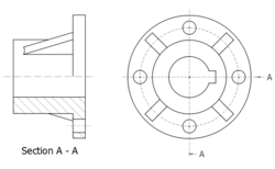
A quarter section view created with the Complex Section tool
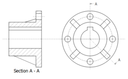
An aligned section view created with the Complex Section tool
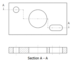
An offset section view created with the Complex Section tool
Usage
- Select a part view and a profile object in the 3D view or Tree view. Profiles are typically Sketches, but any object whose shape can be made into a wire will work.
- There are several ways to invoke the tool:
- Press the
Insert Complex Section button.
- Select the TechDraw →
Insert Complex Section option from the menu.
- Press the
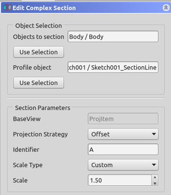
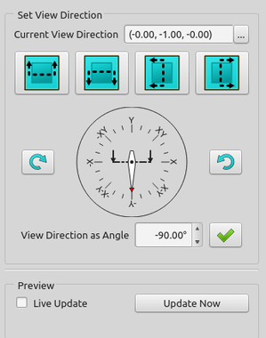
- A task panel will open which will help calculate the various properties. Reasonable starting points for the view Direction are calculated, but these can be changed.
Properties ComplexSection
See also TechDraw SectionView.
Data
Cutting Tool
- DataCutting Tool Wire Object: The document object whose shape will be used to generate the cutting profile.
- DataProjection Strategy: Controls how the cut is performed and how the result is projected on the page:
Offset: Performs a simple cut of the Source shape and projects the result.Aligned: Cuts the Source shape using a tool created from each segment (edge) of the cutting profile. The results of each cut are projected in a vertical or horizontal array, depending on the orientation of the cutting profile.NoParallel: As Aligned, but profile segments which are parallel to the view direction are skipped.
Notes
Scripting
See also: TechDraw API and FreeCAD Scripting Basics.
The ComplexSection tool can be used in macros and from the Python console by using the following functions:
doc = FreeCAD.ActiveDocument
box = doc.Box
profile = doc.Sketch
page = doc.Page

view = doc.addObject("TechDraw::DrawViewPart", "View")
page.addView(view)
view.Source = box
view.Direction = (0.0, 0.0, 1.0)

section = doc.addObject("TechDraw::DrawComplexSection", "ComplexSection")
page.addView(section)
section.BaseView = view
section.CuttingToolWireObject = profile
section.Direction = (0.0, 1.0, 0.0)
section.SectionNormal = (-1.0, 0.0, 0.0)
- Pages: Insert Default Page, Insert Page using Template, Redraw Page, Print All Pages
- Views: Insert View, Insert Active View, Insert Projection Group, Insert Section View, Insert Complex Section View, Insert Detail View, Insert Draft Workbench Object, Insert Arch Workbench Object, Insert Spreadsheet View, Insert Clip Group, Share View, Project Shape
- Stacking: Move view to top of stack, Move view to bottom of stack, Move view up one level, Move view down one level
- Decorations: Hatch Face using Image File, Apply Geometric Hatch to Face, Insert SVG Symbol, Insert Bitmap Image, Turn View Frames On/Off
- Dimensions: Insert Length Dimension, Insert Horizontal Dimension, Insert Vertical Dimension, Insert Radius Dimension, Insert Diameter Dimension, Insert Angle Dimension, Insert 3-Point Angle Dimension, Insert Horizontal Extent Dimension, Insert Vertical Extent Dimension, Link Dimension to 3D Geometry, Insert Balloon Annotation, Insert Axonometric Length Dimension, Insert Landmark Dimension, Adjust Geometric References of Dimension
- Annotations: Insert Annotation, Add Leaderline to View, Insert Rich Text Annotation, Add Cosmetic Vertex, Add Midpoint Vertices, Add Quadrant Vertices, Add Centerline to Faces, Add Centerline between 2 Lines, Add Centerline between 2 Points, Add Cosmetic Line Through 2 points, Add Cosmetic Circle, Change Appearance of Lines, Show/Hide Invisible Edges, Add Welding Information to Leader, Add Surface Finish Symbol, Add Hole or Shaft Tolerances
- Extensions:
- Attributes and modifications: Select Line Attributes, Cascade Spacing and Delta Distance, Change Line Attributes, Extend Line, Shorten Line, Lock/Unlock View, Position Section View, Position Horizontal Chain Dimensions, Position Vertical Chain Dimensions, Position Oblique Chain Dimensions, Cascade Horizontal Dimensions, Cascade Vertical Dimensions, Cascade Oblique Dimensions, Calculate the area of selected faces, Calculate the arc length of selected edges, Customize format label
- Centerlines and threading: Add Circle Centerlines, Add Bolt Circle Centerlines, Add Cosmetic Thread Hole Side View, Add Cosmetic Thread Hole Bottom View, Add Cosmetic Thread Bolt Side View, Add Cosmetic Thread Bolt Bottom View, Add Cosmetic Intersection Vertex(es), Add an offset vertex, Add Cosmetic Circle, Add Cosmetic Arc, Add Cosmetic Circle 3 Points, Add Cosmetic Parallel Line, Add Cosmetic Perpendicular Line
- Dimensions: Create Horizontal Chain Dimensions, Create Vertical Chain Dimensions, Create Oblique Chain Dimensions, Create Horizontal Coordinate Dimensions, Create Vertical Coordinate Dimensions, Create Oblique Coordinate Dimensions, Create Horizontal Chamfer Dimension, Create Vertical Chamfer Dimension, Create Arc Length Dimension, Insert '⌀' Prefix, Insert '〼' Prefix, Remove Prefix, Increase Decimal Places, Decrease Decimal Places
- Export: Export Page as SVG, Export Page as DXF
- Additional: Line Groups, Templates, Hatching, Geometric dimensioning and tolerancing, Preferences
- Getting started
- Installation: Download, Windows, Linux, Mac, Additional components, Docker, AppImage, Ubuntu Snap
- Basics: About FreeCAD, Interface, Mouse navigation, Selection methods, Object name, Preferences, Workbenches, Document structure, Properties, Help FreeCAD, Donate
- Help: Tutorials, Video tutorials
- Workbenches: Std Base, Arch, Assembly, CAM, Draft, FEM, Inspection, Mesh, OpenSCAD, Part, PartDesign, Points, Reverse Engineering, Robot, Sketcher, Spreadsheet, Start, Surface, TechDraw, Test Framework, Web
- Hubs: User hub, Power users hub, Developer hub
