Part Sphere: Difference between revisions
No edit summary |
(Usage, Example, Notes. Changed the Base vector in the scripting example to match the image.) |
||
| Line 35: | Line 35: | ||
<!--T:3--> |
<!--T:3--> |
||
# There are several ways to invoke the command: |
# There are several ways to invoke the command: |
||
#* Press the {{Button|[[Image:Part_Sphere.svg|16px]] [[Part |
#* Press the {{Button|[[Image:Part_Sphere.svg|16px]] [[Part_Sphere|Part Sphere]]}} button. |
||
#* Select the {{MenuCommand|Part → Primitives → [[Image:Part_Sphere.svg|16px]] Sphere}} option from the menu. |
#* Select the {{MenuCommand|Part → Primitives → [[Image:Part_Sphere.svg|16px]] Sphere}} option from the menu. |
||
# A sphere is created. |
|||
# Optionally change the dimensions and {{PropertyData|Placement}} of the sphere by doing one of the following: |
|||
#* Double-click the object in the [[Tree_view|Tree view]]: |
|||
#*# The {{MenuCommand|Geometic Primitives}} task panel opens. |
|||
#*# Change the required properties. |
|||
#*# The object updates dynamically in the [[3D_view|3D view]]. |
|||
#*# Press the {{Button|OK}} button. |
|||
#* Change the properties in the [[Property_editor|Property editor]]. |
|||
#* Change the {{PropertyData|Placement}} with the [[Image:Std_TransformManip.svg|16px]] [[Std_TransformManip|Std TransformManip]] command. |
|||
== Example == |
== Example == |
||
[[ |
[[Image:Part_Sphere_Scripting_Example.png|thumb|Part Sphere scripting example]] |
||
A Part Sphere object with the |
A Part Sphere object created with the [[#Scripting|scripting example]] below is shown here. |
||
== Notes == |
|||
* A Part Sphere can also be created with the [[Image:Part_Primitives.svg|16px]] [[Part_Primitives|Part Primitives]] command. With that command you can specify the dimensions and placement at creating time. |
|||
== Properties == <!--T:4--> |
== Properties == <!--T:4--> |
||
| Line 107: | Line 120: | ||
</translate> |
</translate> |
||
{{Code|code= |
{{Code|code= |
||
sphere.Placement = FreeCAD.Placement(FreeCAD.Vector( |
sphere.Placement = FreeCAD.Placement(FreeCAD.Vector(4, 8, 12), FreeCAD.Rotation(75, 60, 30)) |
||
}} |
}} |
||
<translate> |
<translate> |
||
Revision as of 15:04, 1 March 2022
|
|
| Menu location |
|---|
| Part → Primitives → Sphere |
| Workbenches |
| Part |
| Default shortcut |
| None |
| Introduced in version |
| - |
| See also |
| Part Primitives |
Description
The Part Sphere command creates a parametric sphere solid. It is the result of revolving a circular arc profile around an axis. In the coordinate system defined by its DataPlacement property, the center of the sphere is positioned at the origin, and its axis of revolution is the Z axis.
A Part Sphere can be truncated at the top and/or bottom by changing its DataAngle1 and/or DataAngle2 properties. It can be turned into a segment of a sphere by changing its DataAngle3 property.
Usage
- There are several ways to invoke the command:
- Press the
Part Sphere button.
- Select the Part → Primitives →
Sphere option from the menu.
- Press the
- A sphere is created.
- Optionally change the dimensions and DataPlacement of the sphere by doing one of the following:
- Double-click the object in the Tree view:
- The Geometic Primitives task panel opens.
- Change the required properties.
- The object updates dynamically in the 3D view.
- Press the OK button.
- Change the properties in the Property editor.
- Change the DataPlacement with the
Std TransformManip command.
- Double-click the object in the Tree view:
Example

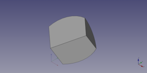
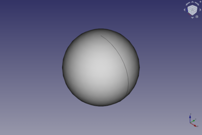
A Part Sphere object created with the scripting example below is shown here.
Notes
- A Part Sphere can also be created with the
Part Primitives command. With that command you can specify the dimensions and placement at creating time.
Properties
See also: Property editor.
A Part Sphere object is derived from a Part Feature object and inherits all its properties. It also has the following additional properties:
Data
Attachment
The object has the same attachment properties as a Part Part2DObject.
Sphere
- DataRadius (
Length): The radius of the sphere. The default is5mm. - DataAngle1 (
Angle): The start angle of the circular arc profile of the sphere. Valid range:-90° <= value <= 90°. May not be equal to DataAngle2. The default is-90°. - DataAngle2 (
Angle): The end angle of the circular arc profile of the sphere. Valid range:-90° <= value <= 90°. May not be equal to DataAngle1. The default is90°. If the total angle of the arc profile is smaller than180°the sphere will be truncated and have a flat face at the top and/or bottom. - DataAngle3 (
Angle): The total angle of revolution of the sphere. Valid range:0° < value <= 360°. The default is360°. If it is smaller than360°the resulting solid will be a segment of a sphere.
Scripting
A Part Sphere can be created using the following function:
sphere = FreeCAD.ActiveDocument.addObject("Part::Sphere", "mySphere")
- Where
mySphereis the user editable name for the object. - The function returns the newly created object.
The label text of the object can be easily changed by
sphere.Label = "new mySphereName"
You can access and modify attributes of the sphere object.
For example, you may wish to modify the radius or the three angles of the sphere.
sphere.Radius = 20
sphere.Angle1 = -30
sphere.Angle2 = 45
sphere.Angle3 = 90
The result will be a part of a sphere, that looks like a piece of cake.
You can change its placement and orientation with:
sphere.Placement = FreeCAD.Placement(FreeCAD.Vector(4, 8, 12), FreeCAD.Rotation(75, 60, 30))
- Primitives: Box, Cylinder, Sphere, Cone, Torus, Tube, Create primitives, Shape builder
- Creation and modification: Extrude, Revolve, Mirror, Fillet, Chamfer, Make face from wires, Ruled Surface, Loft, Sweep, Section, Cross sections, 3D Offset, 2D Offset, Thickness, Projection on surface, Attachment
- Boolean: Make compound, Explode Compound, Compound Filter, Boolean, Cut, Fuse, Common, Connect, Embed, Cutout, Boolean fragments, Slice apart, Slice, XOR
- Measure: Measure Linear, Measure Angular, Measure Refresh, Clear All, Toggle All, Toggle 3D, Toggle Delta
- Getting started
- Installation: Download, Windows, Linux, Mac, Additional components, Docker, AppImage, Ubuntu Snap
- Basics: About FreeCAD, Interface, Mouse navigation, Selection methods, Object name, Preferences, Workbenches, Document structure, Properties, Help FreeCAD, Donate
- Help: Tutorials, Video tutorials
- Workbenches: Std Base, Arch, Assembly, CAM, Draft, FEM, Inspection, Mesh, OpenSCAD, Part, PartDesign, Points, Reverse Engineering, Robot, Sketcher, Spreadsheet, Start, Surface, TechDraw, Test Framework, Web
- Hubs: User hub, Power users hub, Developer hub
