Draft Stretch: Difference between revisions
(Options) |
(Added Preferences) |
||
| Line 57: | Line 57: | ||
* The {{MenuCommand|Continue}} checkbox has no purpose for this command. |
* The {{MenuCommand|Continue}} checkbox has no purpose for this command. |
||
* Press {{KEY|Esc}} or the {{Button|Close}} button to abort the command. |
* Press {{KEY|Esc}} or the {{Button|Close}} button to abort the command. |
||
== Preferences == |
|||
See also: [[Preferences_Editor|Preferences Editor]] and [[Draft_Preferences|Draft Preferences]]. |
|||
* To change the number of decimals used for the input of coordinates: {{MenuCommand|Edit → Preferences... → General → Units → Units settings → Number of decimals}}. |
|||
==Scripting== <!--T:19--> |
==Scripting== <!--T:19--> |
||
Revision as of 18:11, 10 June 2021
|
|
| Menu location |
|---|
| Modification → Stretch |
| Workbenches |
| Draft, Arch |
| Default shortcut |
| None |
| Introduced in version |
| 0.17 |
| See also |
| Draft Offset, Draft Scale |
Description
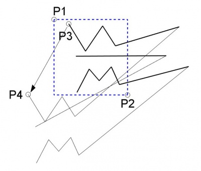
The Draft Stretch tool stretches an object by moving some of its selected vertices. The equivalent action is editing the object and moving the points manually to a new position.
The command can only handle Draft Lines, Draft Wires, Draft Rectangles, Draft BSplines and Draft BezCurves. All other objects are ignored.
Stretching of three wires by enclosing some vertices and moving them to another position
Usage
- Select an object that you wish to stretch.
- Press the
Draft Stretch button. If no object is selected, you will be invited to select one.
- Click a point on the 3D view, or type a coordinate and press the
add point button.
- Click a second point on the 3D view, or type a coordinate and press the
add point button. The first two points define a selection rectangle. The vertices of the original object enclosed by this rectangle become highlighted.
- Click a third point on the 3D view, or type a coordinate and press the
add point button.
- Click a fourth point on the 3D view, or type a coordinate and press the
add point button. The second pair of points define a line, whose distance and direction will be used to stretch the figure attached to the highlighted points.
Options
The single character keyboard shortcuts mentioned here can be changed. See Draft Preferences.
- To manually enter coordinates enter the X, Y and Z component, and press Enter after each. Or you can press the
Enter point button when you have the desired values. It is advisable to move the pointer out of the 3D view before entering coordinates.
- Press R or click the Relative checkbox to toggle relative mode. If relative mode is on, the coordinates of the second point of the displacement are relative to the first point, else they are relative to the coordinate system origin.
- Press G or click the Global checkbox to toggle global mode. If global mode is on, coordinates are relative to the global coordinate system, else they are relative to the working plane coordinate system. introduced in version 0.20
- The Filled checkbox has no purpose for this command.
- The Continue checkbox has no purpose for this command.
- Press Esc or the Close button to abort the command.
Preferences
See also: Preferences Editor and Draft Preferences.
- To change the number of decimals used for the input of coordinates: Edit → Preferences... → General → Units → Units settings → Number of decimals.
Scripting
See also: Autogenerated API documentation and FreeCAD Scripting Basics.
There is no Python method to stretch objects. To emulate the results of the Draft Stretch command geometric properties of objects have to be modified.
- Drafting: Line, Polyline, Fillet, Arc, Arc by 3 points, Circle, Ellipse, Rectangle, Polygon, B-spline, Cubic Bézier curve, Bézier curve, Point, Facebinder, ShapeString, Hatch
- Annotation: Text, Dimension, Label, Annotation styles, Annotation scale
- Modification: Move, Rotate, Scale, Mirror, Offset, Trimex, Stretch, Clone, Array, Polar array, Circular array, Path array, Path link array, Point array, Point link array, Edit, Subelement highlight, Join, Split, Upgrade, Downgrade, Wire to B-spline, Draft to sketch, Set slope, Flip dimension, Shape 2D view
- Draft Tray: Select plane, Set style, Toggle construction mode, AutoGroup
- Snapping: Snap lock, Snap endpoint, Snap midpoint, Snap center, Snap angle, Snap intersection, Snap perpendicular, Snap extension, Snap parallel, Snap special, Snap near, Snap ortho, Snap grid, Snap working plane, Snap dimensions, Toggle grid
- Miscellaneous: Apply current style, Layer, Manage layers, Add a new named group, Move to group, Select group, Add to construction group, Toggle normal/wireframe display, Create working plane proxy, Heal, Show snap toolbar
- Additional: Constraining, Pattern, Preferences, Import Export Preferences, DXF/DWG, SVG, OCA, DAT
- Context menu:
- Layer container: Merge layer duplicates, Add new layer
- Layer: Activate this layer, Select layer contents
- Text: Open hyperlinks
- Wire: Flatten
- Working plane proxy: Write camera position, Write objects state
- Getting started
- Installation: Download, Windows, Linux, Mac, Additional components, Docker, AppImage, Ubuntu Snap
- Basics: About FreeCAD, Interface, Mouse navigation, Selection methods, Object name, Preferences, Workbenches, Document structure, Properties, Help FreeCAD, Donate
- Help: Tutorials, Video tutorials
- Workbenches: Std Base, Arch, Assembly, CAM, Draft, FEM, Inspection, Mesh, OpenSCAD, Part, PartDesign, Points, Reverse Engineering, Robot, Sketcher, Spreadsheet, Surface, TechDraw, Test Framework
- Hubs: User hub, Power users hub, Developer hub
