Part Loft/de: Difference between revisions
(Updating to match new version of source page) |
(Updating to match new version of source page) |
||
| Line 50: | Line 50: | ||
</div> |
</div> |
||
== |
==Options== |
||
| ⚫ | |||
| ⚫ | |||
| ⚫ | |||
| ⚫ | |||
| ⚫ | |||
| ⚫ | |||
| ⚫ | |||
| ⚫ | |||
| ⚫ | |||
====Create solid==== |
====Create solid==== |
||
| Line 87: | Line 73: | ||
Weitere Informationen, wie Profile miteinander verbunden werden, befinden sich auf der Seite [[Part_Loft_Technical_Details/de|Part Ausformung Technische Details]]. |
Weitere Informationen, wie Profile miteinander verbunden werden, befinden sich auf der Seite [[Part_Loft_Technical_Details/de|Part Ausformung Technische Details]]. |
||
</div> |
</div> |
||
==Properties== |
|||
| ⚫ | |||
| ⚫ | |||
| ⚫ | |||
| ⚫ | |||
| ⚫ | |||
| ⚫ | |||
| ⚫ | |||
| ⚫ | |||
| ⚫ | |||
<span id="Limitations"></span> |
<span id="Limitations"></span> |
||
Revision as of 18:00, 4 October 2023
|
Part Ausformung |
| Menüeintrag |
|---|
| Formteil → Ausformung... |
| Arbeitsbereich |
| Part |
| Standardtastenkürzel |
| Keiner |
| Eingeführt in Version |
| 0.13 |
| Siehe auch |
| Part Austragung |
Description
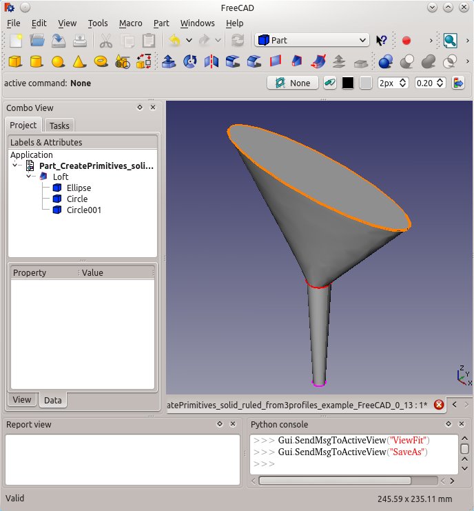
The Part Loft command creates a face, a shell, or a solid shape from two or more profiles (cross-sections).

Usage
- There are several ways to invoke the command:
- Press the
Loft... button.
- Select the Part →
Loft... option from the menu.
- Press the
- The Loft task panel opens.
- In the Available Profiles list on the left select the first profile and click on the right arrow to place it in the Selected profiles list on the right.
- Repeat for the second profile and again if more than two profiles are desired.
- Optionally use the up and down arrows to reorder the selected profiles.
- Define options Create solid, Ruled surface, and Closed.
- Click OK.
Accepted geometry
Das Werkzeug Part Ausformung (Loft) wird verwendet, um aus zwei oder mehr Konturen eine Fläche, Schale oder eine Festkörper-Form zu erstellen. Die Konturen können ein Punkt (Knoten), eine Linie (Kante), ein Kantenzug oder eine Fläche sein. Kanten und Kantenzüge können entweder offen oder geschlossen sein. Es gibt verschiedene Einschränkungen und Schwierigkeiten, siehe unten, jedoch können die Konturen aus den Grundkörpern des Arbeitsbereichs Part, den Objekten des Arbeitsbereichs Draft und aus Skizzen stammen.
- App-Link-Objekte, die auf geeignete Objektarten verweisen und App-Part-Container, die geeignete sichtbare Objekte enthalten, können auch als Profile und Pfade verwendet werden. eingeführt mit Version 0.20
Options
Create solid
Wenn "Festkörper erstellen" auf "wahr" gesetzt ist, erstellt FreeCAD einen Festkörper, wenn die Profile geschlossenen Geometrien sind, wenn auf "falsch" gesetzt, erzeugt FreeCAD stets eine Fläche oder (aus mehreren Flächen) eine Hülle, sowohl aus offenen als auch aus geschlossenen Profilen.
Ruled surface
Wenn "Regelfläche auf " "wahr" gesetzt ist, erstellt FreeCAD eine Fläche, Flächen oder einen Festkörper aus Regelflächen. Regelfläche auf Wikipedia.
Closed
Wenn "Geschlossen" "wahr" ist, versucht FreeCAD, das letzte Profil mit dem ersten Profil zu verbinden, um eine geschlossene Figur zu erzeugen.
Weitere Informationen, wie Profile miteinander verbunden werden, befinden sich auf der Seite Part Ausformung Technische Details.
Properties
See also: Property editor.
A Part Loft object is derived from a Part Feature object and inherits all its properties. It also has the following additional properties:
Data
Loft
- DatenSections (
LinkList): lists the sections used. - DatenSolid (
Bool): true or false (default). True creates a solid. - DatenRuled (
Bool): true or false (default). True creates a ruled surface. - DatenClosed (
Bool): rue or false (default). True creates a closed loft by connecting last to first profile. - DatenMax Degree (
IntegerConstraint): Maximum degree.
Einschränkungen und Schwierigkeiten
A Part Loft has the same limitations as a Part Sweep.
Closed Lofts
- Geschlossene Ausformungen
- Die Ergebnisse geschlossener Ausformungen können unerwartet sein - die Ausformung kann Verdrehungen oder Knicke entwickeln. Ausformen reagiert sehr empfindlich auf die Positionierung der Profile und die Komplexität der Kurven, die erforderlich sind, um die zugehörigen Knoten in allen Profilen zu verbinden.
- Grundkörper: Würfel, Kegel, Zylinder, Kugel, Torus, Grundkörper, Shapebuilder
- Objekte ändern: Boolesche Operationen, Vereinigung, Schnitt, Ausschneiden, Join features, Connect, Embed, Cutout
- Aufteilungswerkzeuge: Boolesche Fragmente, Slice a part, Slice, XOR, Part Defeaturing
- Verbund: Erzeuge Verbund, Verbund auflösen, Compound Filter; Extrudieren, Kanten abrunden, Drehen, Schnitt, Schnitte..., Abschrägen, Spiegelung, Ruled Surface, Sweep, Loft
- Offset-Werkzeuge: 3D Offset, 2D Offset, Dicke, Projection on surface
- Erste Schritte
- Installation: Herunterladen, Windows, Linux, Mac, Zusätzlicher Komponenten, Docker, AppImage, Ubuntu Snap
- Grundlagen: Über FreeCAD, Graphische Oberfläche, Mausbedienung, Auswahlmethoden, Objektname, Programmeinstellungen, Arbeitsbereiche, Dokumentstruktur, Objekteigenschaften, Hilf FreeCAD, Spende
- Hilfe: Tutorien, Video Tutorien
- Arbeitsbereiche: Std Base, Arch, Assembly, CAM, Draft, FEM, Inspection, Mesh, OpenSCAD, Part, PartDesign, Points, Reverse Engineering, Robot, Sketcher, Spreadsheet, Surface, TechDraw, Test Framework
