Part Cylinder: Difference between revisions
(Description) |
(Properties) |
||
| Line 53: | Line 53: | ||
=== Data === |
=== Data === |
||
{{TitleProperty|Attachment}} |
|||
The object has the same attachment properties as a [[Part_Part2DObject#Data|Part Part2DObject]]. |
|||
{{TitleProperty|Cylinder}} |
{{TitleProperty|Cylinder}} |
||
<!--T:20--> |
<!--T:20--> |
||
* {{PropertyData|Radius| |
* {{PropertyData|Radius|Length}}: The radius of the circular arc that defines the cylinder. The default is {{Value|2mm}}. |
||
* {{PropertyData|Height| |
* {{PropertyData|Height|Length}}: The height of the cylinder. The default is {{Value|10mm}}. |
||
* {{PropertyData|Angle|Angle}}: The |
* {{PropertyData|Angle|Angle}}: The angle of the circular arc that defines the cylinder. Valid range: {{Value|0° < value <= 360°}}. The default is {{Value|360°}}. If it is smaller than {{Value|360°}} the resulting solid will be a segment of a cylinder. |
||
{{TitleProperty|Prism}} |
{{TitleProperty|Prism}} |
||
* {{PropertyData|First Angle|Angle}}: Angle in first direction. This is the rotation around the Y axis. {{Version|0.20}} |
|||
* {{PropertyData| |
* {{PropertyData|First Angle|Angle}}: The angle between the extrusion direction of the cylinder and its positive Z axis, measured around its Y axis. The angle is positive towards its positive X axis. Valid range: {{Value|0° <= value < 90°}}. The default is {{Value|0°}}. {{Version|0.20}} |
||
* {{PropertyData|Second Angle|Angle}}: The angle between the extrusion direction of the cylinder and its positive Z axis, measured around its X axis. The angle is positive towards its positive Y axis. Valid range: {{Value|0° <= value < 90°}}. The default is {{Value|0°}}. {{Version|0.20}} |
|||
== Scripting == <!--T:22--> |
== Scripting == <!--T:22--> |
||
Revision as of 09:37, 1 March 2022
|
|
| Menu location |
|---|
| Part → Primitives → Cylinder |
| Workbenches |
| Part |
| Default shortcut |
| None |
| Introduced in version |
| - |
| See also |
| Part Primitives |
Description
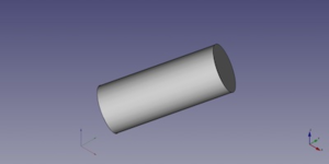
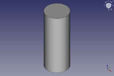
The Part Cylinder command creates a parametric cylinder solid. It is the result of extruding a circular arc along a straight path. In the coordinate system defined by its DataPlacement property, the bottom face of the cylinder lies on the XY plane with its center at the origin.
A Part Cylinder can be turned into a segment of a cylinder by changing its DataAngle property.
Usage
- There are several ways to invoke the command:
- Press the
Cylinder button.
- Select the Part → Primitives →
Cylinder option from the menu.
- Press the
Example

A Part Cylinder object with the values of the bottom scripting example are shown here.
The described placement and orientation changes are not shown because of simplicity for the given example.
Properties
See also: Property editor.
A Part Cylinder object is derived from a Part Feature object and inherits all its properties. It also has the following additional properties:
Data
Attachment
The object has the same attachment properties as a Part Part2DObject.
Cylinder
- DataRadius (
Length): The radius of the circular arc that defines the cylinder. The default is2mm. - DataHeight (
Length): The height of the cylinder. The default is10mm. - DataAngle (
Angle): The angle of the circular arc that defines the cylinder. Valid range:0° < value <= 360°. The default is360°. If it is smaller than360°the resulting solid will be a segment of a cylinder.
Prism
- DataFirst Angle (
Angle): The angle between the extrusion direction of the cylinder and its positive Z axis, measured around its Y axis. The angle is positive towards its positive X axis. Valid range:0° <= value < 90°. The default is0°. introduced in version 0.20 - DataSecond Angle (
Angle): The angle between the extrusion direction of the cylinder and its positive Z axis, measured around its X axis. The angle is positive towards its positive Y axis. Valid range:0° <= value < 90°. The default is0°. introduced in version 0.20
Scripting
A Part Cylinder can be created using the following function:
cylinder = FreeCAD.ActiveDocument.addObject("Part::Cylinder", "myCylinder")
- Where
myCylinderis the user editable name for the object. - The function returns the newly created object.
The label text of the object can be easily changed by
cylinder.Label = "new myCylinderName"
For example, you may wish to modify the width, length or of the start and finish vertex.
cylinder.Radius = 10
cylinder.Height = 25
cylinder.Angle = 270
cylinder.FirstAngle = 30
cylinder.SecondAngle = 45
The result is a three-quarter cylinder.
You can change its placement and orientation with:
cylinder.Placement = FreeCAD.Placement(FreeCAD.Vector(1, 2, 3), FreeCAD.Rotation(75, 60, 30))
- Primitives: Box, Cylinder, Sphere, Cone, Torus, Tube, Create primitives, Shape builder
- Creation and modification: Extrude, Revolve, Mirror, Fillet, Chamfer, Make face from wires, Ruled Surface, Loft, Sweep, Section, Cross sections, 3D Offset, 2D Offset, Thickness, Projection on surface, Attachment
- Boolean: Make compound, Explode Compound, Compound Filter, Boolean, Cut, Fuse, Common, Connect, Embed, Cutout, Boolean fragments, Slice apart, Slice, XOR
- Measure: Measure Linear, Measure Angular, Measure Refresh, Clear All, Toggle All, Toggle 3D, Toggle Delta
- Getting started
- Installation: Download, Windows, Linux, Mac, Additional components, Docker, AppImage, Ubuntu Snap
- Basics: About FreeCAD, Interface, Mouse navigation, Selection methods, Object name, Preferences, Workbenches, Document structure, Properties, Help FreeCAD, Donate
- Help: Tutorials, Video tutorials
- Workbenches: Std Base, Arch, Assembly, CAM, Draft, FEM, Inspection, Mesh, OpenSCAD, Part, PartDesign, Points, Reverse Engineering, Robot, Sketcher, Spreadsheet, Surface, TechDraw, Test Framework
- Hubs: User hub, Power users hub, Developer hub
