Part Wedge: Difference between revisions
(Revising...) |
(Marked this version for translation) |
||
| (10 intermediate revisions by the same user not shown) | |||
| Line 1: | Line 1: | ||
<languages/> |
<languages/> |
||
{{UnfinishedDocu{{#translation:}}}} |
|||
<translate> |
<translate> |
||
| Line 16: | Line 15: | ||
{{GuiCommand |
{{GuiCommand |
||
|Name=Part Wedge |
|Name=Part Wedge |
||
|MenuLocation=Part → Create primitives → Wedge |
|MenuLocation=Part → [[Part_Primitives|Create primitives]] → Wedge |
||
|Workbenches=[[Part_Workbench|Part]] |
|Workbenches=[[Part_Workbench|Part]], [[OpenSCAD_Workbench|OpenSCAD]] |
||
|SeeAlso=[[Part_Primitives|Part Primitives]] |
|SeeAlso=[[Part_Primitives|Part Primitives]] |
||
}} |
}} |
||
| Line 24: | Line 23: | ||
<!--T:2--> |
<!--T:2--> |
||
A [[Image:Part_Wedge.svg|24px]] '''Part Wedge''' is a parametric solid that can be created with the [[Image:Part_Primitives.svg|24px]] [[Part_Primitives|Part Primitives]] command. It has four to six planar faces. It is defined by virtual front and rear main planes on which a rectangular face (the default), a single straight edge or a single vertex is created. These base shapes define the four quadrilateral or triangular faces that connect them. The resulting solid is only a true wedge if one of the base shapes is a rectangular face and the other a straight edge. In the coordinate system defined by its {{PropertyData|Placement}} property, the virtual front and rear main planes of the wedge are plane-parallel to XZ plane and the edges of the base shapes are parallel to the X or Z axis. |
A [[Image:Part_Wedge.svg|24px]] '''Part Wedge''' is a parametric solid that can be created with the [[Image:Part_Primitives.svg|24px]] [[Part_Primitives|Part Primitives]] command. It has four to six planar faces. It is defined by virtual front and rear main planes on which a rectangular face (the default), a single straight edge or a single vertex is created. These base shapes define the four quadrilateral or triangular faces that connect them. The resulting solid is only a true wedge if one of the base shapes is a rectangular face and the other a straight edge. In the coordinate system defined by its {{PropertyData|Placement}} property, the virtual front and rear main planes of the wedge are plane-parallel to XZ plane, and the edges of the base shapes are parallel to the X or Z axis. All its coordinates are relative to that coordinate system. |
||
</translate> |
</translate> |
||
| Line 32: | Line 31: | ||
==Usage== <!--T:12--> |
==Usage== <!--T:12--> |
||
<!--T:15--> |
|||
See [[Part_Primitives#Usage|Part Primitives]]. |
See [[Part_Primitives#Usage|Part Primitives]]. |
||
== Example == |
== Example == <!--T:16--> |
||
<!--T:17--> |
|||
[[Image:Part_Wedge_Scripting_Example.png|thumb|Part Wedge from the scripting example]] |
[[Image:Part_Wedge_Scripting_Example.png|thumb|Part Wedge from the scripting example]] |
||
<!--T:18--> |
|||
A Part Wedge object created with the [[#Scripting|scripting example]] below is shown here. |
A Part Wedge object created with the [[#Scripting|scripting example]] below is shown here. |
||
== |
== Notes == <!--T:19--> |
||
<!--T:20--> |
|||
* The values of the coordinates of the wedge must be such that a valid solid can be create. This means that the front and rear base shapes can both be single edges, but not if they are parallel. And if one of the base shapes is a vertex the other shape must be a rectangular face. |
|||
== Properties == <!--T:21--> |
|||
<!--T:22--> |
|||
See also: [[Property_editor|Property editor]]. |
See also: [[Property_editor|Property editor]]. |
||
<!--T:23--> |
|||
A Part Wedge object is derived from a [[Part_Feature|Part Feature]] object and inherits all its properties. It also has the following additional properties: |
A Part Wedge object is derived from a [[Part_Feature|Part Feature]] object and inherits all its properties. It also has the following additional properties: |
||
=== Data === |
=== Data === <!--T:24--> |
||
<!--T:25--> |
|||
{{TitleProperty|Attachment}} |
|||
<!--T:26--> |
|||
The object has the same attachment properties as a [[Part_Part2DObject#Data|Part Part2DObject]]. |
|||
<!--T:27--> |
|||
{{TitleProperty|Wedge}} |
{{TitleProperty|Wedge}} |
||
<!--T:28--> |
|||
*{{PropertyData|Xmin|Length}}: Base face X minimum value |
|||
* {{PropertyData|Xmin|Distance}}: The lowest X coordinate of the front face of the wedge. The default is {{Value|0mm}}. |
|||
*{{PropertyData|Ymin|Length}}: Wedge height minimum value |
|||
*{{PropertyData| |
* {{PropertyData|Ymin|Distance}}: The Y coordinate of the front face of the wedge. The default is {{Value|0mm}}. |
||
*{{PropertyData| |
* {{PropertyData|Zmin|Distance}}: The lowest Z coordinate of the front face of the wedge. The default is {{Value|0mm}}. |
||
*{{PropertyData| |
* {{PropertyData|X2min|Distance}}: The lowest X coordinate of the rear face of the wedge. The default is {{Value|2mm}}. |
||
*{{PropertyData| |
* {{PropertyData|Z2min|Distance}}: The lowest Z coordinate of the rear face of the wedge. The default is {{Value|2mm}}. |
||
* {{PropertyData|Xmax|Distance}}: The highest X coordinate of the front face of the wedge. The default is {{Value|10mm}}. |
|||
*{{PropertyData|Ymax|Length}}: Wedge height maximum value |
|||
*{{PropertyData| |
* {{PropertyData|Ymax|Distance}}: The Y coordinate of the rear face of the wedge. The default is {{Value|10mm}}. |
||
*{{PropertyData| |
* {{PropertyData|Zmax|Distance}}: The highest Z coordinate of the front face of the wedge. The default is {{Value|10mm}}. |
||
*{{PropertyData| |
* {{PropertyData|X2max|Distance}}: The highest X coordinate of the rear face of the wedge. The default is {{Value|8mm}}. |
||
* {{PropertyData|Z2max|Distance}}: The highest Z coordinate of the rear face of the wedge. The default is {{Value|8mm}}. |
|||
== Scripting == |
== Scripting == <!--T:29--> |
||
<!--T:30--> |
|||
| ⚫ | |||
See also: [https://freecad.github.io/SourceDoc/ Autogenerated API documentation], [[Part_scripting|Part scripting]] and [[FreeCAD_Scripting_Basics|FreeCAD Scripting Basics]]. |
|||
<!--T:31--> |
|||
| ⚫ | |||
</translate> |
</translate> |
||
| Line 71: | Line 92: | ||
<translate> |
<translate> |
||
<!--T:32--> |
|||
* Where {{Incode|myWedge}} is the name for the object |
* Where {{Incode|"myWedge"}} is the name for the object. |
||
* The function returns the newly created object. |
* The function returns the newly created object. |
||
<!--T:33--> |
|||
The {{Incode|Label}} is the user editable name for the object. It can be easily changed by |
|||
Example: |
|||
</translate> |
</translate> |
||
{{Code|code= |
{{Code|code= |
||
import FreeCAD as App |
|||
wedge.Label = "new myWedgeName" |
|||
}} |
|||
<translate> |
|||
doc = App.activeDocument() |
|||
You can access and modify attributes of the {{Incode|wedge}} object. For example, you may wish to modify the minimum or maximum coordinate parameters. |
|||
wedge = doc.addObject("Part::Wedge", "myWedge") |
|||
</translate> |
|||
{{Code|code= |
|||
wedge.Xmin = 1 |
wedge.Xmin = 1 |
||
wedge.Ymin = 2 |
wedge.Ymin = 2 |
||
| Line 96: | Line 116: | ||
wedge.X2max = 10 |
wedge.X2max = 10 |
||
wedge.Z2max = 12 |
wedge.Z2max = 12 |
||
| ⚫ | |||
doc.recompute() |
|||
}} |
}} |
||
<translate> |
<translate> |
||
You can change its placement and orientation with: |
|||
</translate> |
|||
{{Code|code= |
|||
| ⚫ | |||
}} |
|||
<translate> |
|||
<!--T:14--> |
<!--T:14--> |
||
| Line 118: | Line 134: | ||
</translate> |
</translate> |
||
{{ |
{{Part_Tools_navi{{#translation:}}}} |
||
{{Userdocnavi{{#translation:}}}} |
{{Userdocnavi{{#translation:}}}} |
||
Latest revision as of 10:14, 3 March 2022
|
|
| Menu location |
|---|
| Part → Create primitives → Wedge |
| Workbenches |
| Part, OpenSCAD |
| Default shortcut |
| None |
| Introduced in version |
| - |
| See also |
| Part Primitives |
Description
A Part Wedge is a parametric solid that can be created with the
Part Primitives command. It has four to six planar faces. It is defined by virtual front and rear main planes on which a rectangular face (the default), a single straight edge or a single vertex is created. These base shapes define the four quadrilateral or triangular faces that connect them. The resulting solid is only a true wedge if one of the base shapes is a rectangular face and the other a straight edge. In the coordinate system defined by its DataPlacement property, the virtual front and rear main planes of the wedge are plane-parallel to XZ plane, and the edges of the base shapes are parallel to the X or Z axis. All its coordinates are relative to that coordinate system.
Usage
See Part Primitives.
Example

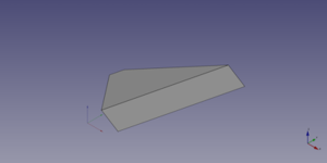
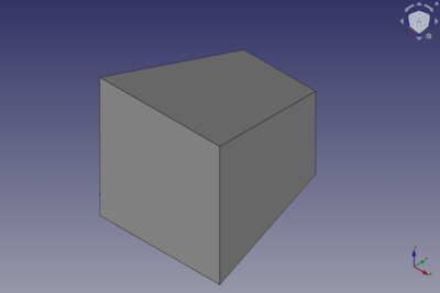
A Part Wedge object created with the scripting example below is shown here.
Notes
- The values of the coordinates of the wedge must be such that a valid solid can be create. This means that the front and rear base shapes can both be single edges, but not if they are parallel. And if one of the base shapes is a vertex the other shape must be a rectangular face.
Properties
See also: Property editor.
A Part Wedge object is derived from a Part Feature object and inherits all its properties. It also has the following additional properties:
Data
Attachment
The object has the same attachment properties as a Part Part2DObject.
Wedge
- DataXmin (
Distance): The lowest X coordinate of the front face of the wedge. The default is0mm. - DataYmin (
Distance): The Y coordinate of the front face of the wedge. The default is0mm. - DataZmin (
Distance): The lowest Z coordinate of the front face of the wedge. The default is0mm. - DataX2min (
Distance): The lowest X coordinate of the rear face of the wedge. The default is2mm. - DataZ2min (
Distance): The lowest Z coordinate of the rear face of the wedge. The default is2mm. - DataXmax (
Distance): The highest X coordinate of the front face of the wedge. The default is10mm. - DataYmax (
Distance): The Y coordinate of the rear face of the wedge. The default is10mm. - DataZmax (
Distance): The highest Z coordinate of the front face of the wedge. The default is10mm. - DataX2max (
Distance): The highest X coordinate of the rear face of the wedge. The default is8mm. - DataZ2max (
Distance): The highest Z coordinate of the rear face of the wedge. The default is8mm.
Scripting
See also: Autogenerated API documentation, Part scripting and FreeCAD Scripting Basics.
A Part Wedge can be created with the addObject() method of the document:
wedge = FreeCAD.ActiveDocument.addObject("Part::Wedge", "myWedge")
- Where
"myWedge"is the name for the object. - The function returns the newly created object.
Example:
import FreeCAD as App

doc = App.activeDocument()

wedge = doc.addObject("Part::Wedge", "myWedge")
wedge.Xmin = 1
wedge.Ymin = 2
wedge.Zmin = 3
wedge.X2min = 4
wedge.Z2min = 6
wedge.Xmax = 15
wedge.Ymax = 20
wedge.Zmax = 55
wedge.X2max = 10
wedge.Z2max = 12
wedge.Placement = App.Placement(App.Vector(1, 2, 3), App.Rotation(75, 60, 30))

doc.recompute()
- Primitives: Box, Cylinder, Sphere, Cone, Torus, Tube, Create primitives, Shape builder
- Creation and modification: Extrude, Revolve, Mirror, Fillet, Chamfer, Make face from wires, Ruled Surface, Loft, Sweep, Section, Cross sections, 3D Offset, 2D Offset, Thickness, Projection on surface, Attachment
- Boolean: Make compound, Explode Compound, Compound Filter, Boolean, Cut, Fuse, Common, Connect, Embed, Cutout, Boolean fragments, Slice apart, Slice, XOR
- Measure: Measure Linear, Measure Angular, Measure Refresh, Clear All, Toggle All, Toggle 3D, Toggle Delta
- Getting started
- Installation: Download, Windows, Linux, Mac, Additional components, Docker, AppImage, Ubuntu Snap
- Basics: About FreeCAD, Interface, Mouse navigation, Selection methods, Object name, Preferences, Workbenches, Document structure, Properties, Help FreeCAD, Donate
- Help: Tutorials, Video tutorials
- Workbenches: Std Base, Arch, Assembly, CAM, Draft, FEM, Inspection, Mesh, OpenSCAD, Part, PartDesign, Points, Reverse Engineering, Robot, Sketcher, Spreadsheet, Surface, TechDraw, Test Framework
- Hubs: User hub, Power users hub, Developer hub
