Part Offset: Difference between revisions
m ({{Docnav|[[Part_CompOffsetTools) |
No edit summary |
||
| (27 intermediate revisions by 7 users not shown) | |||
| Line 1: | Line 1: | ||
{{Template:UnfinishedDocu}} |
|||
<languages/> |
<languages/> |
||
{{UnfinishedDocu{{#translation:}}}} |
|||
<translate> |
<translate> |
||
<!--T:1--> |
<!--T:1--> |
||
{{Docnav |
|||
{{Docnav|[[Part_CompOffsetTools|CompOffsetTools]]|[[Part_Offset2D|2D Offset]]|[[Part_Module|Part]]|IconL=Part_CompOffsetTools.png|IconC=Workbench_Part.svg|IconR=Part_Offset2D.png}} |
|||
|[[Part_CompOffsetTools|CompOffsetTools]] |
|||
|[[Part_Offset2D|Offset2D]] |
|||
|[[Part_Workbench|Part]] |
|||
|IconL=Part_CompOffsetTools.png |
|||
|IconR=Part_Offset2D.svg |
|||
|IconC=Workbench_Part.svg |
|||
}} |
|||
<!--T:2--> |
<!--T:2--> |
||
{{GuiCommand |
|||
| ⚫ | |||
|Name=Part Offset |
|||
|MenuLocation=Part → 3D Offset |
|||
| ⚫ | |||
|Workbenches=[[Part_Workbench|Part]] |
|||
| ⚫ | |||
| ⚫ | |||
}} |
|||
==Description== <!--T:3--> |
==Description== <!--T:3--> |
||
<!--T:4--> |
<!--T:4--> |
||
The |
The [[Image:Part_Offset.svg|24px]] '''Part Offset''' tool creates parallel copies of a selected shape at a certain distance from the base shape, giving a new object. |
||
</translate> |
|||
| ⚫ | |||
| ⚫ | |||
<translate> |
|||
| ⚫ | |||
<!--T:6--> |
<!--T:6--> |
||
Select |
# Select an object to offset. |
||
# Press the {{ |
# Press the {{Button|[[Image:Part_Offset.svg|16px]] [[Part_Offset|3D Offset]]}} button. |
||
# Adjust distance and parameters depending on the original object and the resulting objects validity. |
|||
== |
==Notes== <!--T:24--> |
||
<!--T: |
<!--T:25--> |
||
* [[App_Link|App Link]] objects linked to the appropriate object types and [[App_Part|App Part]] containers with the appropriate visible objects inside can also be used as source objects. {{Version|0.20}} |
|||
| ⚫ | |||
| ⚫ | |||
| ⚫ | |||
<!--T: |
==Examples== <!--T:8--> |
||
| ⚫ | |||
| ⚫ | |||
| ⚫ | |||
| ⚫ | |||
<!--T:18--> |
<!--T:18--> |
||
Object with small offset and rounded ( arc ) corners. |
Object with small offset and rounded ( arc ) corners. |
||
</translate> |
</translate> |
||
| ⚫ | |||
[[Image:PartOffset0.png|400x200px]] → [[Image:PartOffset1.png|400x200px]] |
[[Image:PartOffset0.png|400x200px]] → [[Image:PartOffset1.png|400x200px]] |
||
{{clear}} |
|||
<translate> |
<translate> |
||
| Line 54: | Line 55: | ||
</translate> |
</translate> |
||
<!--T:10--> |
|||
[[Image:PartOffset3.png|400x200px]] |
[[Image:PartOffset3.png|400x200px]] |
||
{{clear}} |
|||
<translate> |
<translate> |
||
| Line 63: | Line 62: | ||
</translate> |
</translate> |
||
<!--T:11--> |
|||
[[Image:PartOffset2.png|400x200px]] |
[[Image:PartOffset2.png|400x200px]] |
||
{{clear}} |
|||
<translate> |
<translate> |
||
| Line 72: | Line 69: | ||
</translate> |
</translate> |
||
<!--T:11--> |
|||
[[Image:PartOffset4.png|400x200px]] |
[[Image:PartOffset4.png|400x200px]] |
||
{{clear}} |
|||
<translate> |
<translate> |
||
| Line 81: | Line 76: | ||
</translate> |
</translate> |
||
<!--T:11--> |
|||
[[Image:PartOffset5.png|400x200px]] |
[[Image:PartOffset5.png|400x200px]] |
||
{{clear}} |
|||
<translate> |
<translate> |
||
| Line 90: | Line 83: | ||
</translate> |
</translate> |
||
<!--T:11--> |
|||
[[Image:PartOffset6.png|400x200px]] |
[[Image:PartOffset6.png|400x200px]] |
||
{{clear}} |
|||
<translate> |
<translate> |
||
| ⚫ | |||
| ⚫ | |||
| ⚫ | |||
| ⚫ | |||
| ⚫ | |||
| ⚫ | |||
| ⚫ | |||
| ⚫ | |||
| ⚫ | |||
<!--T:12--> |
|||
{{Docnav|[[Part_CompOffsetTools|CompOffsetTools]]|[[Part_Offset2D|2D Offset]]|[[Part_Module|Part]]|IconL=Part_CompOffsetTools.png|IconC=Workbench_Part.svg|IconR=Part_Offset2D.png}} |
|||
<!--T: |
<!--T:12--> |
||
{{Docnav |
|||
| ⚫ | |||
|[[Part_CompOffsetTools|CompOffsetTools]] |
|||
|[[Part_Offset2D|Offset2D]] |
|||
<!--T:14--> |
|||
|[[Part_Workbench|Part]] |
|||
| ⚫ | |||
|IconL=Part_CompOffsetTools.png |
|||
|IconR=Part_Offset2D.svg |
|||
|IconC=Workbench_Part.svg |
|||
}} |
|||
</translate> |
</translate> |
||
| ⚫ | |||
{{clear}} |
|||
| ⚫ | |||
Latest revision as of 21:11, 2 June 2022
This documentation is not finished. Please help and contribute documentation.
GuiCommand model explains how commands should be documented. Browse Category:UnfinishedDocu to see more incomplete pages like this one. See Category:Command Reference for all commands.
See WikiPages to learn about editing the wiki pages, and go to Help FreeCAD to learn about other ways in which you can contribute.
|
|
| Menu location |
|---|
| Part → 3D Offset |
| Workbenches |
| Part |
| Default shortcut |
| None |
| Introduced in version |
| - |
| See also |
| Part Thickness, Part 2D Offset |
Description
The Part Offset tool creates parallel copies of a selected shape at a certain distance from the base shape, giving a new object.
Usage
- Select an object to offset.
- Press the
3D Offset button.
- Adjust distance and parameters depending on the original object and the resulting objects validity.
Notes
- App Link objects linked to the appropriate object types and App Part containers with the appropriate visible objects inside can also be used as source objects. introduced in version 0.20
Examples
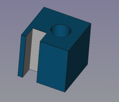
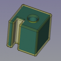
Object with small offset and rounded ( arc ) corners.
Same object with sharp ( intersection ) corners.
Same object with thick distance overfilling the front left gap and allowed intersections.
Arbitrary shape ( draft poly as wire ) with a 3D Offset ( ignores MODE param )
same shape with a 3D Offset as SKIN and filled offset
filled offset with 2 Cylinders creating boolean cuts. Cylinder A goes through the FILL whilst Cylinder B only goes thru the FILL and NOT through the source 2D shape.
Properties
- DataOffset: Distance to offset the faces of the shape.
- DataMode: Mode of creation. Skin creates a new shape around the source shape. Pipe (todo). RectoVerso (todo).
- DataJoin type: How the new corners are build up. Intersection gives sharp corners by linear extension of the edges. Arc and Tangent give rounded corners.
- Option: Intersection: Allows offsets pointing inwards to "overflow" the gap by intersecting the resulting shape until opposite faces are reached.
- Option: Self Intersection: (todo).
- Option: Fill Offset: When the shape was 2 dimensional, the gap between the 2 shapes gets filled. The fill is now a solid, hence the source shape is not a solid. Thus boolean operations may lead to strange results. (see example below).
- Primitives: Box, Cylinder, Sphere, Cone, Torus, Tube, Create primitives, Shape builder
- Creation and modification: Extrude, Revolve, Mirror, Fillet, Chamfer, Make face from wires, Ruled Surface, Loft, Sweep, Section, Cross sections, 3D Offset, 2D Offset, Thickness, Projection on surface, Attachment
- Boolean: Make compound, Explode Compound, Compound Filter, Boolean, Cut, Fuse, Common, Connect, Embed, Cutout, Boolean fragments, Slice apart, Slice, XOR
- Measure: Measure Linear, Measure Angular, Measure Refresh, Clear All, Toggle All, Toggle 3D, Toggle Delta
- Getting started
- Installation: Download, Windows, Linux, Mac, Additional components, Docker, AppImage, Ubuntu Snap
- Basics: About FreeCAD, Interface, Mouse navigation, Selection methods, Object name, Preferences, Workbenches, Document structure, Properties, Help FreeCAD, Donate
- Help: Tutorials, Video tutorials
- Workbenches: Std Base, Arch, Assembly, CAM, Draft, FEM, Inspection, Mesh, OpenSCAD, Part, PartDesign, Points, Reverse Engineering, Robot, Sketcher, Spreadsheet, Surface, TechDraw, Test Framework
- Hubs: User hub, Power users hub, Developer hub


