Part Offset2D: Difference between revisions
No edit summary |
|||
| (34 intermediate revisions by 9 users not shown) | |||
| Line 1: | Line 1: | ||
<languages/> |
|||
<translate> |
<translate> |
||
<!--T:55--> |
|||
{{GuiCommand|Name=Part Offset2D|MenuLocation=Part → 2D Offset|Workbenches=[[Part Module|Part]]|SeeAlso=[[Part_Offset|Part_Offset]], [[Part_Thickness|Part Thickness]], [[Draft_Offset|Draft Offset]]}} |
|||
{{Docnav |
|||
|[[Part_Offset|Offset]] |
|||
|[[Part_Thickness|Thickness]] |
|||
|[[Part_Workbench|Part]] |
|||
|IconL=Part_Offset.svg |
|||
|IconR=Part_Thickness.svg |
|||
|IconC=Workbench_Part.svg |
|||
}} |
|||
<!--T:23--> |
|||
{{GuiCommand |
|||
|Name=Part Offset2D |
|||
|MenuLocation=Part → 2D Offset |
|||
|Workbenches=[[Part_Workbench|Part]] |
|||
|Version=0.17 |
|||
|SeeAlso=[[Part_Offset|Part Offset 3D]], [[Part_Thickness|Part Thickness]], [[Draft_Offset|Draft Offset]] |
|||
}} |
|||
==Description== <!--T:60--> |
|||
<!--T:25--> |
|||
The [[Image:Part_Offset2D.svg|24px]] '''Part Offset2D''' tool constructs a wire, parallel to the original wire, at a certain distance from it. Or enlarges/shrinks a planar face, similarly. |
|||
<!--T:26--> |
|||
The wire/face must be planar. There can be multiple wires in one object, not necessarily coplanar. |
|||
</translate> |
|||
[[image:Part Offset2D Demo.png|600px]] |
[[image:Part Offset2D Demo.png|600px]] |
||
<translate> |
|||
==Usage== <!--T:61--> |
|||
...UNDER CONSTRUCTION... |
|||
<!--T:27--> |
|||
==Description== |
|||
# Select an object to offset. |
|||
Part 2D Offset constructs a wire, parallel to the original wire, at a certain distance from it. Or enlarges/shrinks a planar face, similarly. |
|||
# Press the {{Button|[[Image:Part_Offset2D.svg|16px]] [[Part_Offset2D|2D Offset]]}} button. |
|||
# Set up the offset in the [[Task_panel|Task Panel]]. |
|||
# Press {{Button|OK}}. |
|||
==Notes== <!--T:62--> |
|||
The wire/face must be planar. There can be multiple wires in one object, not necessarily coplanar. |
|||
<!--T:63--> |
|||
==How to use== |
|||
* [[App_Link|App Link]] objects linked to the appropriate object types and [[App_Part|App Part]] containers with the appropriate visible objects inside can also be used as source objects. {{Version|0.20}} |
|||
# Select an object to offset |
|||
# Invoke Part Offset2D command. |
|||
# Set up the offset in Task Panel, and accept the dialog. |
|||
==Known issues== <!--T:43--> |
|||
A 2D Offset parametric object is created. Original objects are switched to wireframe display mode. |
|||
<!--T:54--> |
|||
==Properties== |
|||
* Most of non-default modes will only work with OCC 7.0.0 or later. |
|||
<!--T:44--> |
|||
{{TitleProperty|Offset}} |
|||
* Using the tool can crash FreeCAD (see next point). On Windows, these crashes are converted to exceptions and don't generally cause FreeCAD to close; on other OS'es it is not the case, so it is advisable to save project before attempting to use the tool. Ellipses are not handled either. |
|||
* {{PropertyData|Source}}: Link to original shape |
|||
<!--T:45--> |
|||
* {{PropertyData|Value}} The distance to enlarge the wire/face by. If negative, the wire/face is shrunk instead. |
|||
* Enlarging faces with circular holes by an amount large enough to cause holes to close up, a crash occurs (OCC 7.0.0). The problem seems to be specific to circles; other shapes seem to close out properly. |
|||
<!--T:46--> |
|||
* {{PropertyData|Mode}} ("Pipe" or "Skin"): sets how non-closed wires are processed. If "Pipe", the wire is outlined as if it was an extremely thin closed contour. If "Skin", an open wire is created. |
|||
* When offsetting circles that have non-zero Placement, the result is placed wrongly. (OCC 7.0.0) |
|||
<!--T:47--> |
|||
[[image:Part Offset2D Mode.png|600px]] |
|||
* When offsetting circles, sometimes they are offset in unexpected direction (e.g. inward instead of outward). (OCC 7.0.0) |
|||
<!--T:48--> |
|||
* {{PropertyData|Join}} ("Arc", "Tangent", "Intersection"): sets the behavior around kinks. If "Arc", offset segments are connected with an arc of circle, centered at the vertex. "Tangent" is unsupported on OCC7.0.0. "Intersection": offset segments are extended till they intersect. |
|||
* Fill="true" doesn't work when collectively offsetting open wires in "Skin" mode |
|||
<!--T:49--> |
|||
[[image:Part Offset2D Join.png|600px]] |
|||
* "Tangent" join mode doesn't work (OCC 7.0.0) |
|||
<!--T:50--> |
|||
* {{PropertyData|Intersection}} ("false", "true"): sets if multiple wires are treated collectively or independently. If "false", wires are offset independently, intersections between resulting wires are ignored. If "true", the wires are offset in collective manner. |
|||
* Offsetting wires made of single line segment is not supported (because line segment doesn't define a plane). Single line segments cannot participate in collective offset either. |
|||
==Properties== <!--T:29--> |
|||
[[image:Part Offset2D Intersection.png|600px]] |
|||
<!--T:30--> |
|||
Only wires within a compound are coupled. For example, if the structure is like compound(wire1, wire2, compound(wire3, wire4)), wire1 and wire2 will be treated collectively, but independently from wire3 and wire4. Likewise, wire3 and wire4 are treated collectively, but independently of wire1+wire2. |
|||
* {{PropertyData|Source}}: Link to original shape |
|||
<!--T:31--> |
|||
Also, in collective mode, directions of wires are important, and influence direction of offset. This is in tight relationship with how holes in faces are treated. |
|||
* {{PropertyData|Value}}: The distance to enlarge the wire/face by. If negative, the wire/face is shrunk instead. |
|||
<!--T:32--> |
|||
Wires being treated collectively must be coplanar. Wires being offset independently don't have to be coplanar. |
|||
* {{PropertyData|Mode}} ("Pipe" or "Skin"): sets how non-closed wires are processed. If "Pipe", the wire is outlined as if it was an extremely thin closed contour. If "Skin", an open wire is created. |
|||
</translate> |
|||
* {{PropertyData|Fill}} ("false", "true"): if "true", the space between original wire/face and the offset is filled with a face. |
|||
:[[image:Part Offset2D Mode.png|600px]] |
|||
<translate> |
|||
<!--T:34--> |
|||
[[image:Part Offset2D Fill.png|600px]] |
|||
* {{PropertyData|Join}} ("Arc", "Tangent", "Intersection"): sets the behavior around kinks. If "Arc", offset segments are connected with an arc of circle, centered at the vertex. "Tangent" is unsupported on OCC7.0.0. "Intersection": offset segments are extended till they intersect. |
|||
</translate> |
|||
==Known issues== |
|||
:[[image:Part Offset2D Join.png|600px]] |
|||
<translate> |
|||
<!--T:36--> |
|||
* Using the tool can crash FreeCAD (see next point). On Windows, these crashes are converted to exceptions and don't generally cause FreeCAD to close; on other OS'es it is not the case. So, it is advised to save project before attempting to use the tool. |
|||
* {{PropertyData|Intersection}} ("false", "true"): sets if multiple wires are treated collectively or independently. If "false", wires are offset independently, intersections between resulting wires are ignored. If "true", the wires are offset in collective manner. |
|||
</translate> |
|||
* Enlarging faces with circular holes by an amount large enough to cause holes to close up, a crash occurs (OCC 7.0.0). The problem seems to be specific to circles; other shapes seem to close out properly. |
|||
:[[image:Part Offset2D Intersection.png|600px]] |
|||
<translate> |
|||
<!--T:38--> |
|||
* when offsetting circles that have non-zero Placement, the result is placed wrongly. (OCC 7.0.0) |
|||
:Only wires within a compound are coupled. For example, if the structure is like compound(wire1, wire2, compound(wire3, wire4)), wire1 and wire2 will be treated collectively, but independently from wire3 and wire4. Likewise, wire3 and wire4 are treated collectively, but independently of wire1+wire2. |
|||
<!--T:39--> |
|||
* when offsetting circles, sometimes they are offset in unexpected direction (e.g. inward instead of outward). (OCC 7.0.0) |
|||
:Also, in collective mode, directions of wires are important, and influence direction of offset. This is in tight relationship with how holes in faces are treated. |
|||
<!--T:40--> |
|||
* Fill="true" doesn't work when collectively offsetting open wires in "Skin" mode |
|||
:Wires being treated collectively must be coplanar. Wires being offset independently don't have to be coplanar. |
|||
<!--T:41--> |
|||
* "Tangent" join mode doesn't work (OCC 7.0.0) |
|||
* {{PropertyData|Fill}} ("false", "true"): if "true", the space between original wire/face and the offset is filled with a face. |
|||
</translate> |
|||
* Offsetting wires made of single line segment is not supported (because line segment doesn't define a plane). Single line segments cannot participate in collective offset either. |
|||
:[[image:Part Offset2D Fill.png|600px]] |
|||
<translate> |
|||
==Scripting== |
==Scripting== <!--T:51--> |
||
<!--T:52--> |
|||
The tool can by used in [[macros]] and from the python console by using the following function: |
|||
The tool can by used in [[Macros|macros]] and from the [[Python|Python]] console by using the following function: |
|||
</translate> |
</translate> |
||
{{code|code= |
{{code|code= |
||
| Line 75: | Line 129: | ||
<translate> |
<translate> |
||
<!--T:53--> |
|||
2D offset is also available as a method of Part.Shape. Example: |
2D offset is also available as a method of Part.Shape. Example: |
||
</translate> |
</translate> |
||
| Line 102: | Line 157: | ||
<translate> |
<translate> |
||
==Version== <!--T:22--> |
|||
<!--T:59--> |
|||
The tool was introduced in FreeCAD v0.17.8350. Most of non-default modes will only work with OCC 7.0.0 or later. |
|||
{{Docnav |
|||
|[[Part_Offset|Offset]] |
|||
|[[Part_Thickness|Thickness]] |
|||
|[[Part_Workbench|Part]] |
|||
|IconL=Part_Offset.svg |
|||
|IconR=Part_Thickness.svg |
|||
|IconC=Workbench_Part.svg |
|||
}} |
|||
</translate> |
</translate> |
||
{{Part Tools navi{{#translation:}}}} |
|||
{{Userdocnavi{{#translation:}}}} |
|||
{{clear}} |
{{clear}} |
||
<languages/> |
|||
Latest revision as of 21:12, 2 June 2022
|
|
| Menu location |
|---|
| Part → 2D Offset |
| Workbenches |
| Part |
| Default shortcut |
| None |
| Introduced in version |
| 0.17 |
| See also |
| Part Offset 3D, Part Thickness, Draft Offset |
Description
The Part Offset2D tool constructs a wire, parallel to the original wire, at a certain distance from it. Or enlarges/shrinks a planar face, similarly.
The wire/face must be planar. There can be multiple wires in one object, not necessarily coplanar.
Usage
- Select an object to offset.
- Press the
2D Offset button.
- Set up the offset in the Task Panel.
- Press OK.
Notes
- App Link objects linked to the appropriate object types and App Part containers with the appropriate visible objects inside can also be used as source objects. introduced in version 0.20
Known issues
- Most of non-default modes will only work with OCC 7.0.0 or later.
- Using the tool can crash FreeCAD (see next point). On Windows, these crashes are converted to exceptions and don't generally cause FreeCAD to close; on other OS'es it is not the case, so it is advisable to save project before attempting to use the tool. Ellipses are not handled either.
- Enlarging faces with circular holes by an amount large enough to cause holes to close up, a crash occurs (OCC 7.0.0). The problem seems to be specific to circles; other shapes seem to close out properly.
- When offsetting circles that have non-zero Placement, the result is placed wrongly. (OCC 7.0.0)
- When offsetting circles, sometimes they are offset in unexpected direction (e.g. inward instead of outward). (OCC 7.0.0)
- Fill="true" doesn't work when collectively offsetting open wires in "Skin" mode
- "Tangent" join mode doesn't work (OCC 7.0.0)
- Offsetting wires made of single line segment is not supported (because line segment doesn't define a plane). Single line segments cannot participate in collective offset either.
Properties
- DataSource: Link to original shape
- DataValue: The distance to enlarge the wire/face by. If negative, the wire/face is shrunk instead.
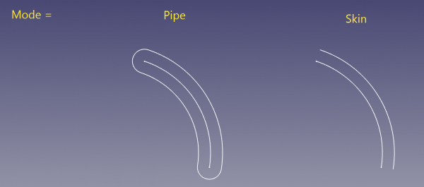
- DataMode ("Pipe" or "Skin"): sets how non-closed wires are processed. If "Pipe", the wire is outlined as if it was an extremely thin closed contour. If "Skin", an open wire is created.
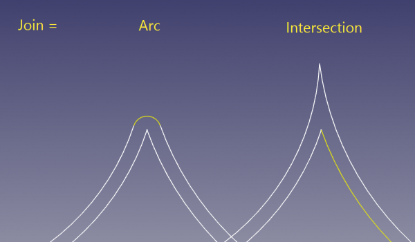
- DataJoin ("Arc", "Tangent", "Intersection"): sets the behavior around kinks. If "Arc", offset segments are connected with an arc of circle, centered at the vertex. "Tangent" is unsupported on OCC7.0.0. "Intersection": offset segments are extended till they intersect.
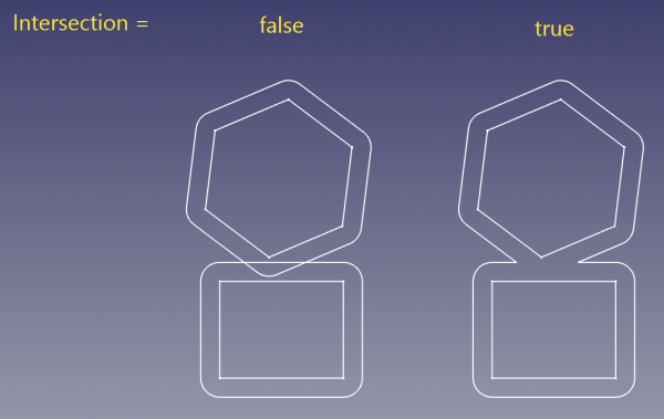
- DataIntersection ("false", "true"): sets if multiple wires are treated collectively or independently. If "false", wires are offset independently, intersections between resulting wires are ignored. If "true", the wires are offset in collective manner.
- Only wires within a compound are coupled. For example, if the structure is like compound(wire1, wire2, compound(wire3, wire4)), wire1 and wire2 will be treated collectively, but independently from wire3 and wire4. Likewise, wire3 and wire4 are treated collectively, but independently of wire1+wire2.
- Also, in collective mode, directions of wires are important, and influence direction of offset. This is in tight relationship with how holes in faces are treated.
- Wires being treated collectively must be coplanar. Wires being offset independently don't have to be coplanar.
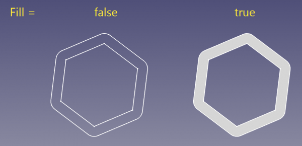
- DataFill ("false", "true"): if "true", the space between original wire/face and the offset is filled with a face.
Scripting
The tool can by used in macros and from the Python console by using the following function:
f = App.ActiveDocument.addObject("Part::Offset2D", "Offset2D")
f.Source =  #some object
f.Value = 10.0
2D offset is also available as a method of Part.Shape. Example:
import Part
circle = Part.Circle().toShape()
enlarged_circle = circle.makeOffset2D(10.0)
Part.show(circle)
Part.show(enlarged_circle)
# makeOffset2D(offset, join = 0, fill = False, openResult = false, intersection = false)
#
# * offset: distance to expand the shape by.
#
# * join: method of offsetting non-tangent joints. 0 = arcs, 1 = tangent, 2 =
# intersection
#
# * fill: if true, the output is a face filling the space covered by offset. If
# false, the output is a wire/face.
#
# * openResult: True for "Skin" mode; False for Pipe mode.
#
# * intersection: collective offset
#
# Returns: result of offsetting (wire or face or compound of those). Compounding
# structure follows that of source shape.
- Primitives: Box, Cylinder, Sphere, Cone, Torus, Tube, Create primitives, Shape builder
- Creation and modification: Extrude, Revolve, Mirror, Fillet, Chamfer, Make face from wires, Ruled Surface, Loft, Sweep, Section, Cross sections, 3D Offset, 2D Offset, Thickness, Projection on surface, Attachment
- Boolean: Make compound, Explode Compound, Compound Filter, Boolean, Cut, Fuse, Common, Connect, Embed, Cutout, Boolean fragments, Slice apart, Slice, XOR
- Measure: Measure Linear, Measure Angular, Measure Refresh, Clear All, Toggle All, Toggle 3D, Toggle Delta
- Getting started
- Installation: Download, Windows, Linux, Mac, Additional components, Docker, AppImage, Ubuntu Snap
- Basics: About FreeCAD, Interface, Mouse navigation, Selection methods, Object name, Preferences, Workbenches, Document structure, Properties, Help FreeCAD, Donate
- Help: Tutorials, Video tutorials
- Workbenches: Std Base, Arch, Assembly, CAM, Draft, FEM, Inspection, Mesh, OpenSCAD, Part, PartDesign, Points, Reverse Engineering, Robot, Sketcher, Spreadsheet, Start, Surface, TechDraw, Test Framework, Web
- Hubs: User hub, Power users hub, Developer hub


