Robot Workbench/zh-cn: Difference between revisions
(Created page with "示例如何使用基本机器人中 Robot6Axis 的来模拟工业六轴机器人。机器人模块依赖于零件模块而不是其他模块。它的工作原理主要是基...") |
(Created page with "=== 基本机器人事项 === 创建机器人。如果你不想指定另一个的话,那么默认使用的是 Puma 560 机器人。") |
||
| Line 49: | Line 49: | ||
}} |
}} |
||
=== |
=== 基本机器人事项 === |
||
创建机器人。如果你不想指定另一个的话,那么默认使用的是 Puma 560 机器人。 |
|||
create the robot. If you do not specify another kinematic it becomes a Puma 560 |
|||
{{Code|code= |
{{Code|code= |
||
rob = Robot6Axis() |
rob = Robot6Axis() |
||
Revision as of 12:44, 16 October 2017

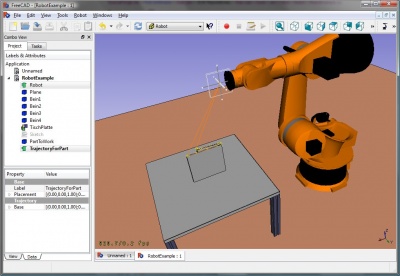
机器人工作台是一个用于模仿工业 Robot 6-Axis 的工具,就像 Kuka。 用它可以完成以下任务:
- 用机器人和工件设立一个模拟环境
- 创建和填补轨迹
- 将一个 CAD 零件的特征分解为轨迹
- 模拟机器人的运动及其可达性
- 将轨迹导出为机器人程序文件
你可以从这儿找到例子: Example files 或者去参考 Robot tutorial.
工具
这里提供了设置机器人的主要命令。
机器人
创建和管理六轴机器人的工具
轨迹
创建和操作轨迹的工具。分为两种:参数性的和非参数性的。
非参数性轨迹
 创建轨迹: 在场景中插入一个新机器人
 设置默认方位: 设置默认的方位航向点
 设置速度参数默认值: 设置默认的航向点创建
 插入航向点: 从当前机器人位置向轨迹中插入一个航向点
 插入航向点: 从当前的鼠标位置向轨迹中插入一个航向点
参数性轨迹
脚本编程
本节是由 https://github.com/FreeCAD/FreeCAD_sf_master/blob/master/src/Mod/Robot/RobotExample.py 产生出来的,你可以直接使用这个文件。
示例如何使用基本机器人中 Robot6Axis 的来模拟工业六轴机器人。机器人模块依赖于零件模块而不是其他模块。它的工作原理主要是基本类型的布局,矢量和矩阵。因此我们只需要:
from Robot import *
from Part import *
from FreeCAD import *
基本机器人事项
创建机器人。如果你不想指定另一个的话,那么默认使用的是 Puma 560 机器人。
rob = Robot6Axis()
print rob
accessing the axis and the Tcp. Axes go from 1-6 and are in degree:
Start = rob.Tcp
print Start
print rob.Axis1
move the first axis of the robot:
rob.Axis1 = 5.0
the Tcp has changed (forward kinematic)
print rob.Tcp
move the robot back to start position (reverse kinematic):
rob.Tcp = Start
print rob.Axis1
the same with axis 2:
rob.Axis2 = 5.0
print rob.Tcp
rob.Tcp = Start
print rob.Axis2
Waypoints:
w = Waypoint(Placement(),name="Pt",type="LIN")
print w.Name,w.Type,w.Pos,w.Cont,w.Velocity,w.Base,w.Tool
generate more. The trajectory always finds automatically a unique name for the waypoints
l = [w]
for i in range(5):
  l.append(Waypoint(Placement(Vector(0,0,i*100),Vector(1,0,0),0),"LIN","Pt"))
create a trajectory
t = Trajectory(l)
print t
for i in range(7):
  t.insertWaypoints(Waypoint(Placement(Vector(0,0,i*100+500),Vector(1,0,0),0),"LIN","Pt"))
see a list of all waypoints:
print t.Waypoints

del rob,Start,t,l,w
Working with the document objects
Working with the robot document objects: first create a robot in the active document
if(App.activeDocument() == None):App.newDocument()

App.activeDocument().addObject("Robot::RobotObject","Robot")
Define the visual representation and the kinematic definition (see Robot 6-Axis and VRML Preparation for Robot Simulation for details about that)
App.activeDocument().Robot.RobotVrmlFile = App.getResourceDir()+"Mod/Robot/Lib/Kuka/kr500_1.wrl"
App.activeDocument().Robot.RobotKinematicFile = App.getResourceDir()+"Mod/Robot/Lib/Kuka/kr500_1.csv"
start positon of the Axis (only that which differ from 0)
App.activeDocument().Robot.Axis2 = -90
App.activeDocument().Robot.Axis3 = 90
retrieve the Tcp position
pos = FreeCAD.getDocument("Unnamed").getObject("Robot").Tcp
move the robot
pos.move(App.Vector(-10,0,0))
FreeCAD.getDocument("Unnamed").getObject("Robot").Tcp = pos
create an empty Trajectory object in the active document
App.activeDocument().addObject("Robot::TrajectoryObject","Trajectory")
get the Trajectory
t = App.activeDocument().Trajectory.Trajectory
add the actual TCP position of the robot to the trajectory
StartTcp = App.activeDocument().Robot.Tcp
t.insertWaypoints(StartTcp)
App.activeDocument().Trajectory.Trajectory = t
print App.activeDocument().Trajectory.Trajectory
insert some more Waypoints and the start point at the end again:
for i in range(7):
  t.insertWaypoints(Waypoint(Placement(Vector(0,1000,i*100+500),Vector(1,0,0),i),"LIN","Pt"))

t.insertWaypoints(StartTcp) # end point of the trajectory
App.activeDocument().Trajectory.Trajectory = t
print App.activeDocument().Trajectory.Trajectory
Simulation
To be done.....
Exporting the trajectory
The trajectory is exported by Python. That means for every control cabinet type there is a post-processor Python module. Here is in detail the Kuka post-processor described
from KukaExporter import ExportCompactSub

ExportCompactSub(App.activeDocument().Robot,App.activeDocument().Trajectory,'D:/Temp/TestOut.src')
and that's kind of how it's done:
for w in App.activeDocument().Trajectory.Trajectory.Waypoints:
	(A,B,C) = (w.Pos.Rotation.toEuler())
	print ("LIN {X %.3f,Y %.3f,Z %.3f,A %.3f,B %.3f,C %.3f} ; %s"%(w.Pos.Base.x,w.Pos.Base.y,w.Pos.Base.z,A,B,C,w.Name))
Tutorials