Part Box/en: Difference between revisions
(Updating to match new version of source page) |
(Updating to match new version of source page) |
||
| Line 19: | Line 19: | ||
== Description == |
== Description == |
||
The |
The [[Image:Part_Box.svg|24px]] '''Part Box''' command creates a parametric box solid, a [https://en.wikipedia.org/wiki/Cuboid#Rectangular_cuboid rectangular cuboid]. In the coordinate system defined by its {{PropertyData|Placement}} property, the bottom face of the box lies on the XY plane with its front left corner at the origin, and its front edge parallel to the X axis. |
||
[[Image: |
[[Image:Part_Box_Example.png|400px]] |
||
== Usage == |
== Usage == |
||
# Switch to the [[Image:Workbench_Part.svg|16px]] [[Part_Workbench|Part Workbench]] |
|||
# There are several ways to invoke the command: |
# There are several ways to invoke the command: |
||
#* Press the {{Button|[[Image:Part_Box.svg|16px]] |
#* Press the {{Button|[[Image:Part_Box.svg|16px]] [[Part_Box|Part Box]]}} button. |
||
#* Select the {{MenuCommand|Part → Primitives → [[Image:Part_Box.svg|16px]] Cube}} from the menu |
#* Select the {{MenuCommand|Part → Primitives → [[Image:Part_Box.svg|16px]] Cube}} option from the menu. |
||
# The box is created. |
|||
# Optionally change the dimensions and {{PropertyData|Placement}} of the box by doing one of the following: |
|||
#* Double-click the object in the [[Tree_view|Tree view]]: |
|||
#*# The {{MenuCommand|Geometic Primitives}} task panel opens. |
|||
#*# Change one or more properties. |
|||
#*# The object is dynamically updated in the [[3D_view|3D view]]. |
|||
#*# Press the {{Button|OK}} button. |
|||
#* Change the properties in the [[Property_editor|Property editor]]. |
|||
#* Change the {{PropertyData|Placement}} with the [[Image:Std_TransformManip.svg|16px]] [[Std_TransformManip|Std TransformManip]] command. |
|||
== Example == |
|||
'''Result:''' The default result is a box with an equal length, width and height of 10 mm. It is attached to the global xy-plane and one edge is coincident with the global z-axis. |
|||
[[Image:Part_Box_Scripting_Example.png|thumb|Part Box from the scripting example]] |
|||
The box properties can later be edited, either in the property editor or by double-clicking on the box in the model tree. |
|||
A Part Box object created with the [[#Scripting|scripting example]] below is shown here. |
|||
== Notes == |
|||
* A Part Box can also be created with the [[Image:Part_Primitives.svg|16px]] [[Part_Primitives|Part Primitives]] command. With that command you can specify the dimensions and placement at creation time. |
|||
== Properties == |
== Properties == |
||
See also: [[Property_editor|Property editor]]. |
|||
{{Properties_Title|Box}} |
|||
A Part Box object is derived from a [[Part_Feature|Part Feature]] object and inherits all its properties. It also has the following additional properties: |
|||
| ⚫ | |||
| ⚫ | |||
=== Data === |
|||
| ⚫ | |||
{{TitleProperty|Attachment}} |
|||
The object has the same attachment properties as a [[Part_Part2DObject#Data|Part Part2DObject]]. |
|||
{{TitleProperty|Box}} |
|||
| ⚫ | |||
| ⚫ | |||
| ⚫ | |||
== Scripting == |
== Scripting == |
||
See also: [https://freecad.github.io/SourceDoc/ Autogenerated API documentation], [[Part_scripting|Part scripting]] and [[FreeCAD_Scripting_Basics|FreeCAD Scripting Basics]]. |
|||
| ⚫ | |||
| ⚫ | |||
{{Code|code= |
{{Code|code= |
||
| Line 53: | Line 79: | ||
* The function returns the newly created object. |
* The function returns the newly created object. |
||
Example: |
|||
You can access and modify attributes of the {{Incode|box}} object. For example, you may wish to modify the length, width and height parameters. |
|||
{{Code|code= |
{{Code|code= |
||
import FreeCAD as App |
|||
| ⚫ | |||
| ⚫ | |||
| ⚫ | |||
}} |
|||
doc = App.activeDocument() |
|||
You can change its placement with: |
|||
box = doc.addObject("Part::Box", "myBox") |
|||
{{Code|code= |
|||
| ⚫ | |||
| ⚫ | |||
| ⚫ | |||
| ⚫ | |||
| ⚫ | |||
doc.recompute() |
|||
}} |
}} |
||
| Line 77: | Line 105: | ||
}} |
}} |
||
{{ |
{{Part_Tools_navi{{#translation:}}}} |
||
{{Userdocnavi{{#translation:}}}} |
{{Userdocnavi{{#translation:}}}} |
||
Revision as of 09:47, 3 March 2022
|
|
| Menu location |
|---|
| Part → Primitives → Cube |
| Workbenches |
| Part |
| Default shortcut |
| None |
| Introduced in version |
| - |
| See also |
| Part Primitives |
Description
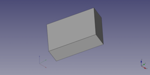
The Part Box command creates a parametric box solid, a rectangular cuboid. In the coordinate system defined by its DataPlacement property, the bottom face of the box lies on the XY plane with its front left corner at the origin, and its front edge parallel to the X axis.
Usage
- There are several ways to invoke the command:
- Press the
Part Box button.
- Select the Part → Primitives →
Cube option from the menu.
- Press the
- The box is created.
- Optionally change the dimensions and DataPlacement of the box by doing one of the following:
- Double-click the object in the Tree view:
- The Geometic Primitives task panel opens.
- Change one or more properties.
- The object is dynamically updated in the 3D view.
- Press the OK button.
- Change the properties in the Property editor.
- Change the DataPlacement with the
Std TransformManip command.
- Double-click the object in the Tree view:
Example

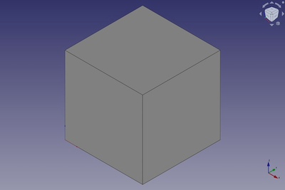
A Part Box object created with the scripting example below is shown here.
Notes
- A Part Box can also be created with the
Part Primitives command. With that command you can specify the dimensions and placement at creation time.
Properties
See also: Property editor.
A Part Box object is derived from a Part Feature object and inherits all its properties. It also has the following additional properties:
Data
Attachment
The object has the same attachment properties as a Part Part2DObject.
Box
- DataLength (
Length): The length of the box. This is the dimension in its X direction. The default is10mm. - DataWidth (
Length): The width of the box. This is the dimension in its Y direction. The default is10mm. - DataHeight (
Length): The height of the box. This is dimension in its Z direction. The default is10mm.
Scripting
See also: Autogenerated API documentation, Part scripting and FreeCAD Scripting Basics.
A Part Box can be created with the addObject() method of the document:
box = FreeCAD.ActiveDocument.addObject("Part::Box", "myBox")
- Where
"myBox"is the name for the object. - The function returns the newly created object.
Example:
import FreeCAD as App

doc = App.activeDocument()

box = doc.addObject("Part::Box", "myBox")
box.Length = 4
box.Width = 8
box.Height = 12
box.Placement = App.Placement(App.Vector(1, 2, 3), App.Rotation(75, 60, 30))

doc.recompute()
- Primitives: Box, Cylinder, Sphere, Cone, Torus, Tube, Create primitives, Shape builder
- Creation and modification: Extrude, Revolve, Mirror, Fillet, Chamfer, Make face from wires, Ruled Surface, Loft, Sweep, Section, Cross sections, 3D Offset, 2D Offset, Thickness, Projection on surface, Attachment
- Boolean: Make compound, Explode Compound, Compound Filter, Boolean, Cut, Fuse, Common, Connect, Embed, Cutout, Boolean fragments, Slice apart, Slice, XOR
- Measure: Measure Linear, Measure Angular, Measure Refresh, Clear All, Toggle All, Toggle 3D, Toggle Delta
- Getting started
- Installation: Download, Windows, Linux, Mac, Additional components, Docker, AppImage, Ubuntu Snap
- Basics: About FreeCAD, Interface, Mouse navigation, Selection methods, Object name, Preferences, Workbenches, Document structure, Properties, Help FreeCAD, Donate
- Help: Tutorials, Video tutorials
- Workbenches: Std Base, Arch, Assembly, CAM, Draft, FEM, Inspection, Mesh, OpenSCAD, Part, PartDesign, Points, Reverse Engineering, Robot, Sketcher, Spreadsheet, Start, Surface, TechDraw, Test Framework, Web
- Hubs: User hub, Power users hub, Developer hub
