Measurement Of Angles On Holes/de: Difference between revisions
(Created page with "Beim Bemaßen von Bohrungswinkeln kann man die vertikalen und horizontalen Mittellinien, die man in den Eigenschaften der Ansicht mit "False/True" einstellen kann, nicht nutze...") |
(Created page with "== Ausführung ==") |
||
| Line 15: | Line 15: | ||
Beim Bemaßen von Bohrungswinkeln kann man die vertikalen und horizontalen Mittellinien, die man in den Eigenschaften der Ansicht mit "False/True" einstellen kann, nicht nutzen. Man benötigt Hilfslinien bzw. -punkte. |
Beim Bemaßen von Bohrungswinkeln kann man die vertikalen und horizontalen Mittellinien, die man in den Eigenschaften der Ansicht mit "False/True" einstellen kann, nicht nutzen. Man benötigt Hilfslinien bzw. -punkte. |
||
== |
== Ausführung == |
||
1. Setting center lines on holes: |
1. Setting center lines on holes: |
||
Revision as of 11:06, 28 April 2020
| Topic |
|---|
| TechDraw |
| Level |
| Base |
| Time to complete |
| 1 minute |
| Authors |
| AnHi |
| FreeCAD version |
| 0.19 |
| Example files |
| None |
| See also |
| None |
Einleitung
Dieses Tutorial erklärt, wie man mit TechDraw Workbench Winkel an z.B. schrägen Bohrungen bemaßen kann.
Beim Bemaßen von Bohrungswinkeln kann man die vertikalen und horizontalen Mittellinien, die man in den Eigenschaften der Ansicht mit "False/True" einstellen kann, nicht nutzen. Man benötigt Hilfslinien bzw. -punkte.
Ausführung
1. Setting center lines on holes:
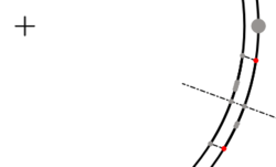
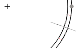
There are some possibilities to create a center line for holes. At first the lines or points on the hole must be selected as shown below. Second, the following tools can be used from the toolbar to create the center line:
Above: created with which creates centerlines between 2 points
Above: created with which creates centerlines between 2 lines
In the dialog box choice "Ausgerichtet / Aligned" for achses out of main achses. "Erweitert um / Extend by" means the length of the center line beyond of the body line in the drawing. With "Shift Horiz." and "Shift Vert." the center line can move in horizontal or vertical direction, if is necessary. "Stil" means the figure of center line.

Above: dialog box
The created center line can change. Select the center line and press the button or
from the tool bar which you have created the center line. Delete the center line only with
from the tool bar after selecting the center line.
2. Setting angles:
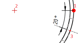
Quadrant points select with from the tool bar. Next select the points as show below and use
from the tool bar to create the angle. Other succession create other angles.
Is there no catching point on the center line change "ISO count" in the properties.

Above: Succession of selection
- Blätter (Seiten): Neues Zeichnungsblatt aus der Standardvorlage erstellen, Neues Zeichnungsblatt aus einer Vorlage erstellen, Seite neu zeichnen, Alle Seiten drucken
- Ansichten: Ansicht einfügen, Aktive (3D-)Ansicht einfügen, Ansichtengruppe einfügen, Schnittansicht einfügen, Komplexe Schnittansicht einfügen, Detailansicht einfügen, Objekt des Arbeitsbereichs Draft einfügen, Objekt des Arbeitsbereichs Arch einfügent, Tabellenansicht einfügen, Ausschnittsgruppe einfügen, Ansicht teilen, Form projizieren
- Stapeln: Ansicht auf die Stapeloberseite bewegen, Ansicht auf die Stapelunterseite bewegen, Ansicht um eine Ebene nach oben bewegen, Ansicht um eine Ebene nach unten bewegen
- Verzierungen: Fläche mit Muster aus einer Bilddatei schraffieren, Fläche mit einer geometrischen Schraffur versehen, SVG-Zeichnungselement einfügen, Bitmap-Grafik einfügen, Ansichtsrahmen ein- oder ausschalten
- Maßeinträge: Längenmaß einfügen, Horizontales Maß einfügen, Vertikales Maß einfügen, Radienmaß einfügen, Durchmessermaß einfügen, Winkelmaß einfügen, Winkelmaß über 3 Punkte einfügen, Maß für die horizontale Ausdehnung einfügen, Maß für die Vertikale Ausdehnung einfügen, Maß mit 3D-Geometrie verknüpfen, Hinweisfeld einfügen, Axonometrisches Längenmaß, Maß zwischen Orientierungspunkten einfügen, Maßreferenzen reparieren
- Anmerkungen: Anmerkung einfügen, Hinweislinie zur Ansicht hinzufügen, Rich-Text-Anmerkung einfügen, Hilfspunkt hinzufügen, Kantenmittelpunkte hinzufügen, Quadrantengrenzpunkte hinzufügen, Mittellinie zu Fläche(n) hinzufügen, Mittellinie zwischen 2 Linien hinzufügen, Mittellinie zwischen 2 Punkte hinzufügen, Hilfslinie durch 2 Punkte hinzufügen, Hilfskreis hinzufügen, Liniendarstellung ändern, Ausgeblendete Kanten ein-/ausblenden, Hinzufügen von Schweißinformationen zur Hinweislinie, Oberflächensymbol erstellen, Wellen- oder Bohrungspassung hinzufügen
- Ergänzungen:
- Merkmale und Änderungen: Linienmerkmale, Zeilenabstand und Längendifferenz auswählen, Linienmerkmale ändern, Linie verlängern, Linie kürzen, Ansicht fixieren/lösen, Schnittansicht ausrichten, Horizontale Kettenmaße anordnen, Vertikale Kettenmaße anordnen, Schräge Kettenmaße anordnen, Horizontale Maße anordnen, Vertikale Maße anordnen, Schräge Maße anordnen, Flächeninhalt der ausgewählten Flächen berechnen, Bogenlänge der ausgewählten Kanten berechnen, Formatierung anpassen
- Mittellinien und Gewinde: Kreismittellinien hinzufügen, Lochkreismittellinien hinzufügen, Hilfslinien für Innengewinde in Seitenansicht hinzufügen, Hilfslinien für Innengewinde in Achsansicht hinzufügen, Hilfslinien für Außengewinde in Seitenansicht hinzufügen, Hilfslinien für Außengewinde in Achsansicht hinzufügen, Hilfsschnittpunkte hinzufügen, Add an offset vertex, Hilfskreis hinzufügen, Hilfsbogen hinzufügen, Hilfskreis über 3 Punkte hinzufügen, Parallele Hilfslinie hinzufügen, Senkrechte Hilfslinie hinzufügen
- Maße: Horizontale Maßkette erstellen, Vertikale Maßkette erstellen, Schräge Maßketten erstellen, Horizontale Koordinatenmaße erstellen, Vertikale Koordinatenmaße erstellen, Schräge Koordinatenmaße erstellen, Horizontales Maß an Fase erstellen, Vertikales Maß an Fase erstellen, Bogenmaß erstellen, '⌀'-Symbol einfügen, '□'-Symbol einfügen, Präfixsymbol entfernen, Dezimalstellenanzahl erhöhen, Dezimalstellenanzahl verringern
- Exportieren: Seite als SVG-Datei exportieren, Seite als DXF-Datei exportieren
- Zusätzliche Funktionen: Liniengruppen, Vorlagen, Schraffieren, Form- und Lagetolerierung, Einstellungen
- Erste Schritte
- Installation: Herunterladen, Windows, Linux, Mac, Zusätzlicher Komponenten, Docker, AppImage, Ubuntu Snap
- Grundlagen: Über FreeCAD, Graphische Oberfläche, Mausbedienung, Auswahlmethoden, Objektname, Programmeinstellungen, Arbeitsbereiche, Dokumentstruktur, Objekteigenschaften, Hilf FreeCAD, Spende
- Hilfe: Tutorien, Video Tutorien
- Arbeitsbereiche: Std Base, Arch, Assembly, CAM, Draft, FEM, Inspection, Mesh, OpenSCAD, Part, PartDesign, Points, Reverse Engineering, Robot, Sketcher, Spreadsheet, Start, Surface, TechDraw, Test Framework, Web

