Macro WorkFeatures/de: Difference between revisions
(Created page with "==Externe Arbeitsbereiche==") |
No edit summary |
||
| (38 intermediate revisions by 4 users not shown) | |||
| Line 12: | Line 12: | ||
}} |
}} |
||
<span id="Description"></span> |
|||
==Beschreibung== |
==Beschreibung== |
||
Werkzeug Hilfsprogramm (Deutsch: ''ArbeitsFunktionen'') zum Erstellen von Punkten (Mittelpunkte, Kreismittelpunkt, Mittelpunkt von Objekt(en)...), |
|||
| ⚫ | |||
| ⚫ | |||
| ⚫ | |||
Werkzeug-Hilfsprogramm zum Erstellen von: |
|||
* Punkten (Mittelpunkte, Kreismittelpunkte, Mittelpunkte von Objekten...), |
|||
| ⚫ | |||
| ⚫ | |||
| ⚫ | |||
[[File:WF.png|640px]] |
[[File:WF.png|640px]] |
||
{{Caption|WorkFeatures}} |
{{Caption|WorkFeatures}} |
||
<span id="Uses"></span> |
|||
==Anwendungen== |
==Anwendungen== |
||
'''ArbeitsFunktionen''' |
'''ArbeitsFunktionen''' |
||
| Line 42: | Line 46: | ||
|} |
|} |
||
''' |
'''Punkte Reiter''' |
||
{| |
{| |
||
|[[File:Macro WorkFeatures 03.png|200px|left]] |
|[[File:Macro WorkFeatures 03.png|200px|left]] |
||
| |
| |
||
*''' |
*'''Punkte Reiter''' |
||
* {{KEY| |
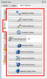
* {{KEY|Objekt(e) Zentrum}}: Erzeugt einen Punkt an der Zentrumsposition aller ausgewählten Objekte. |
||
* {{KEY| |
* {{KEY|Linie(n) Zentrum}} : Erstelle einen Punkt an der Mittelpunktsposition jeder ausgewählten Linie(n). |
||
* {{KEY|Line(s) Extrema}} : |
* {{KEY|Line(s) Extrema}} : Erstelle Punkte am Start- und Endposition jeder ausgewählten Linie(n). |
||
* {{KEY|Circle(s) Center}} : Create a Point at center location of each selected Circle(s) or Arc(s). |
* {{KEY|Circle(s) Center}} : Create a Point at center location of each selected Circle(s) or Arc(s). |
||
* {{KEY|Point along Line}} : Create a Point on a line at some distance of the extremity |
* {{KEY|Point along Line}} : Create a Point on a line at some distance of the extremity point selected. |
||
* '''SpinBox''' : enter the displacement value |
* '''SpinBox''' : enter the displacement value |
||
* {{KEY|Face(s) Center}} : Create a Point at center location of each selected Face(s). |
* {{KEY|Face(s) Center}} : Create a Point at center location of each selected Face(s). |
||
| Line 161: | Line 165: | ||
|} |
|} |
||
= |
<span id="Script"></span> |
||
==Skript== |
|||
After downloading the file compressed here |
|||
Nach dem Herunterladen der komprimierten Datei, hier |
|||
| ⚫ | |||
| ⚫ | |||
| ⚫ | |||
| ⚫ | |||
you must unzip the zip and copy all the files in your macro directory. |
|||
musst du die zip Datei entpacken und alle Dateien in dein Makroverzeichnis kopieren. |
|||
'''PS: Dieses Makro befindet sich noch in der Entwicklung. Bitte besuche diese Seite, um sicher zu sein, dass du die neueste Version hast.''' |
|||
'''PS:This macro is still in development please visit this page for commonly be sure to have the latest version.''' |
|||
<br /> |
<br /> |
||
[[File:Macro Work Features GitHub 00.png|center|640px| |
[[File:Macro Work Features GitHub 00.png|center|640px|Herunterladen in GitHub klicke auf die Download ZIP Schaltfläche]] |
||
{{clear}} |
{{clear}} |
||
Verwende den [[Image:AddonManager.svg|24px]] [[Std_AddonMgr/de|Addon-Manager]] {{MenuCommand|Menü → Werkzeuge → Addon-Manager}} zur einfachen Installation von WorkFeatures und anderen interessanten Makros |
|||
Hier geht es zur ausführlichen [[How_to_install macros/de|Anleitung zur Installation von Makros]]. |
|||
Here for [[How to install macros|How to install macros]] detailed |
|||
<span id="Examples"></span> |
|||
==Beispiele== |
==Beispiele== |
||
<span id="Cutting_tools"></span> |
|||
===Schneidwerkzeuge=== |
===Schneidwerkzeuge=== |
||
'''Einstellung der Schneidwerkzeuge:''' Wähle ein zu schneidendes Objekt, eine Schnittlinie und eine Referenzebene. |
|||
'''Setting of the Cutting tools:''' Select an object to cut, a cutting line and a reference Plane. |
|||
Winkel ist ein Winkel zwischen der Schneidebene und der Referenzebene. |
|||
Angle is an angle between the cutting Plane and the Ref. Plane. |
|||
Dicke ist die Breite der Schnittebene. |
|||
Thickness is the wide of the of the cutting Plane. |
|||
<center> |
<center> |
||
<gallery widths="400" heights="250"> |
<gallery widths="400" heights="250"> |
||
Image:CuttingSettings.jpg |
Image:CuttingSettings.jpg |
||
|Hier haben wir einen Zylinder ausgewählt. |
|||
Image:CuttingResult.jpg|The result will be : the cylinder is then cut in two parts! |
|||
Image:CuttingResult.jpg |
|||
|Das Ergebnis wird sein: der Zylinder wird dann in zwei Teile geschnitten! |
|||
</gallery> |
</gallery> |
||
</center> |
</center> |
||
{{clear}} |
{{clear}} |
||
<center> |
<center> |
||
''' |
'''Execute practical example''' |
||
<gallery widths="400" heights="250"> |
<gallery widths="400" heights="250"> |
||
Image:Macro Work Features Cutting 01.png|Select the '''Tab {{KEY|Plane}}''' |
Image:Macro Work Features Cutting 01.png|Select the '''Tab {{KEY|Plane}}''' |
||
| Line 227: | Line 236: | ||
<center> |
<center> |
||
<gallery widths="400" heights="250"> |
<gallery widths="400" heights="250"> |
||
Image:Macro Work Features Cutting 09.png| |
Image:Macro Work Features Cutting 09.png| du kannst auch Winkel und Dicke für deinen Schnitt angeben. |
||
</gallery> |
</gallery> |
||
</center> |
</center> |
||
{{clear}} |
{{clear}} |
||
<span id="Concentric_constraint_between_two_non_cylindrical_parts"></span> |
|||
===Konzentrische Beschränkung zwischen zwei nicht zylindrischen Teilen=== |
===Konzentrische Beschränkung zwischen zwei nicht zylindrischen Teilen=== |
||
<center> |
<center> |
||
<gallery widths="500" heights="500"> |
<gallery widths="500" heights="500"> |
||
Image:Concentric Constraint Between two non cylindrical parts.gif |
|||
Image:Concentric Constraint Between two non cylindrical parts.gif|How to Constraint Between two non cylindrical parts.<br />'''1 :''' The original object to modify.<br />'''2 :''' Objective center two square tubes.<br />'''3 :''' Select the first object and in the menu '''Axis 1/2''' click "Object(s)" X, Y, Z Axes.<br />'''4 :''' Same procedure for the second object.<br />'''5 :''' Click on button '''Draw style''' and onto "Wireframe",<br />'''6 :''' for clarify the view.<br />'''7 :''' Select the object to center and his axis created.<br />'''8 :''' Click the button '''Draft Move'''<br />'''9 :''' and select the first axis to move on the second axis.<br />'''10 :''' Restore normal view with on button '''Draw style''' and onto '''As is'''.<br />'''11 :''' Click the first object moved and correct the position with "Combo view > Data > Placement".<br />'''12 :''' Select the object created by WorkFeature (contener axis) and delete it.<br />'''13 :''' The object weshed.<br />'''14 :''' The result. |
|||
</gallery> |
</gallery> |
||
{| class="wikitable" |
|||
{| cellpadding=5 style="border:1px solid #BBB" |
|||
|Wie eine Beschränkung zwischen zwei nicht zylindrischen Teilen herstellen.<br />'''1 :''' Das zu ändernde Originalobjekt.<br />'''2 :''' Zielmitte zweier Vierkantrohre.<br />'''3 :''' Wähle das erste Objekt und klicke im Menü '''Achse 1/2''' auf "Objekt(e)" X, Y, Z Axes.<br />'''4 :''' Gleiche Vorgehensweise für das zweite Objekt.<br />'''5 :''' Klicke auf Schaltfläche '''Draw style''' und auf "Wireframe",<br />'''6 :''' zur Verdeutlichung der Ansicht.<br />'''7 :''' Wähle das zu zentrierende Objekt und seine erstellte Achse.<br />'''8 :''' Klicke die Schaltfläche '''Draft Move'''<br />'''9 :''' und wähle die erste Achse, die auf der zweiten Achse verschoben werden soll.<br />'''10 :''' Normalansicht mit der Taste '''Zeichenstil''' und auf '''Original'''wiederherstellen.<br />'''11 :''' Klicke das erste verschobene Objekt und korrigiere die Position mit "Comboansicht > Daten > Positionierung".<br />'''12 :''' Wähle das von WorkFeature erstellte Objekt (Contener Achse) aus und lösche es.<br />'''13 :''' Das Objekt verschwindet.<br />'''14 :''' Das Ergebnis. |
|||
|} |
|||
</center> |
</center> |
||
{{clear}} |
{{clear}} |
||
<span id="Rotation_Object"></span> |
|||
===Rotationsobjekt=== |
===Rotationsobjekt=== |
||
| Line 250: | Line 268: | ||
{{clear}} |
{{clear}} |
||
<span id="Plane_on_face_tangent"></span> |
|||
[[Category:Addons/de]] |
|||
===Ebene auf Flächentangente=== |
|||
[[Category:User Documentation/de]] |
|||
<center> |
<center> |
||
| Line 261: | Line 279: | ||
== |
==Verweise== |
||
Die Forumsdiskussion [http://forum.freecadweb.org/viewtopic.php?f=22&t=9056 MACRO:Work Feature 2014_12] |
|||
<span id="External_workbenches"></span> |
|||
==Externe Arbeitsbereiche== |
==Externe Arbeitsbereiche== |
||
FreeCAD |
FreeCAD Arbeitsbereiche sind einfach in [[Python/de|Python]] zu programmieren, daher gibt es viele Leute, die zusätzliche Arbeitsbereiche außerhalb der FreeCAD Hauptentwickler entwickeln. |
||
Die [[external workbenches/de|Externe Arbeitsbereiche]] Seite enthält einige Informationen und Tutorien zu einigen von ihnen, und das [https://github.com/FreeCAD/FreeCAD-addons/ FreeCAD Erweiterungen] Projekt zielt darauf ab, sie zu sammeln und einfach aus FreeCAD heraus zu installieren. |
|||
Neue Arbeitsbereiche sind in der Entwicklung, bleib dran! |
|||
New workbenches are in development, stay tuned! |
|||
<span id="Latest_version"></span> |
|||
==Neueste Version== |
==Neueste Version== |
||
Latest revision as of 19:20, 26 April 2023
| Beschreibung |
|---|
| Werkzeug Hilfsprogramm zum Erstellen von Punkten, Achsen, Ebenen...und andere nützliche Funktionen. Versionsmakro : 05/2019 Datum der letzten Änderung : 01.05.2019 FreeCAD version : Alle Herunterladen : Werkzeugleistensymbol Autor: rentlau_64 |
| Autor |
| rentlau_64 |
| Herunterladen |
| Werkzeugleistensymbol |
| Links |
| Makros Rezepte Wie installiere ich Makros So passen Sie Symbolleisten an |
| Macro-Version |
| 05/2019 |
| Datum der letzten Änderung |
| 01.05.2019 |
| FreeCAD-Version(s) |
| Alle |
| Standardverknüpfung |
| None |
| Siehe auch |
| None |
Beschreibung
Werkzeug-Hilfsprogramm zum Erstellen von:
- Punkten (Mittelpunkte, Kreismittelpunkte, Mittelpunkte von Objekten...),
- Achsen (aus 2 Punkten, Normalen von Ebenen...),
- Ebenen (aus 3 Punkten, aus einer Achse und einem Punkt...)
- Und viele andere nützliche Funktionen, die dir die Erstellung deines Projekts erleichtern. Dieses Hilfsprogramm befindet sich in der Combo-Ansicht mit der Bezeichnung Work Features (Deutsch: ArbeitsFunktionen).
WorkFeatures
Anwendungen
ArbeitsFunktionen
-
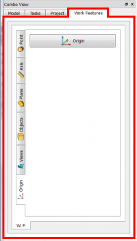
Nach dem Aktivieren von Work Features bewegt sich das Werkzeug im Combo Ansichtsfensters nach links.
-
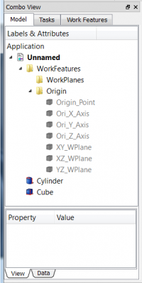
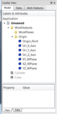
Jede Verwendung und jedes Tag, das einer Funktionsgruppe entspricht, ist eine Gruppe, die im Namen des verwendeten Kennzeichens erstellt wurde. Der Ursprung von Achse, Punkt und Ebene wird direkt auf ausgeblendet gesetzt.
-
Du kannst allgemeine Befehle EINGEBEN UND VERWENDEN, um die erstellte Funktion sichtbar zu machen.
Beispieltaste Space oder wähle dein Objekt aus und rechtsklicke mit der Maus und klicke auf "Auswahl ausblenden" oder "Auswahl anzeigen" .
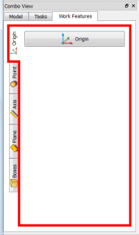
Ursprung Reiter
 |
|
Punkte Reiter
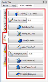
Axis Tab
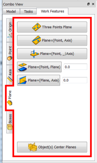
Plane Tab
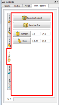
Objects Tab
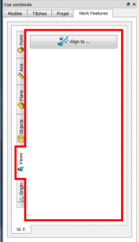
Views Tab
 |
|
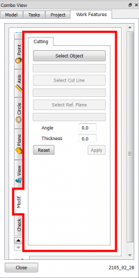
Modif. Tab
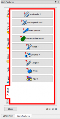
Check. Tab
Skript
Nach dem Herunterladen der komprimierten Datei, hier
Herunterladen der neusten Version auf GitHub , musst du die zip Datei entpacken und alle Dateien in dein Makroverzeichnis kopieren.
PS: Dieses Makro befindet sich noch in der Entwicklung. Bitte besuche diese Seite, um sicher zu sein, dass du die neueste Version hast.
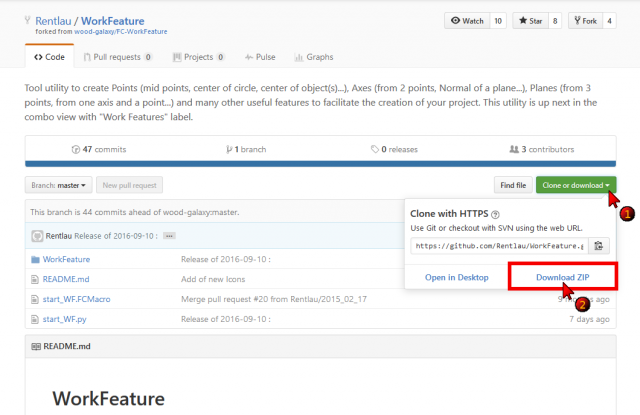
Verwende den Addon-Manager Menü → Werkzeuge → Addon-Manager zur einfachen Installation von WorkFeatures und anderen interessanten Makros
Hier geht es zur ausführlichen Anleitung zur Installation von Makros.
Beispiele
Schneidwerkzeuge
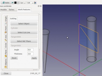
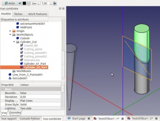
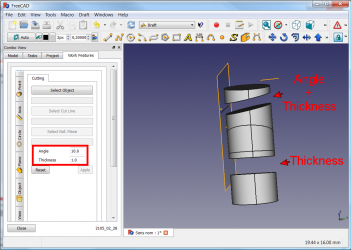
Einstellung der Schneidwerkzeuge: Wähle ein zu schneidendes Objekt, eine Schnittlinie und eine Referenzebene. Winkel ist ein Winkel zwischen der Schneidebene und der Referenzebene. Dicke ist die Breite der Schnittebene.
Execute practical example
-
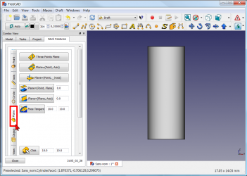
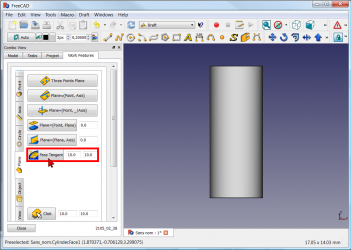
Select the Tab Plane
-
and click the Plane button
(you can change the dimensions of the plane (Default: 10 x 10)).
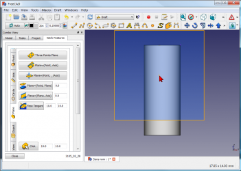
-
click you work object. The plane is created tangent of the object (here a cylinder)
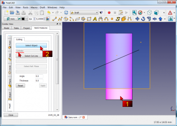
-
click the Tab Modif, and
1 : click your object for cutting
2 : click the Select object button (here the cylinder and then name is displayed)
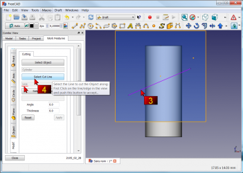
-
3 : click your line for cutting your cylinder
4 : click the Select Cut Line (then name is displayed) -
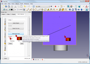
5 : click the work plane
6 : click the Select Ref. Plane button (then name is displayed)
-
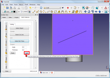
click the Apply button
-
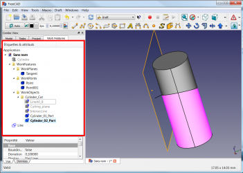
The operation is completed and all operations are preserved.
-
du kannst auch Winkel und Dicke für deinen Schnitt angeben.
Konzentrische Beschränkung zwischen zwei nicht zylindrischen Teilen
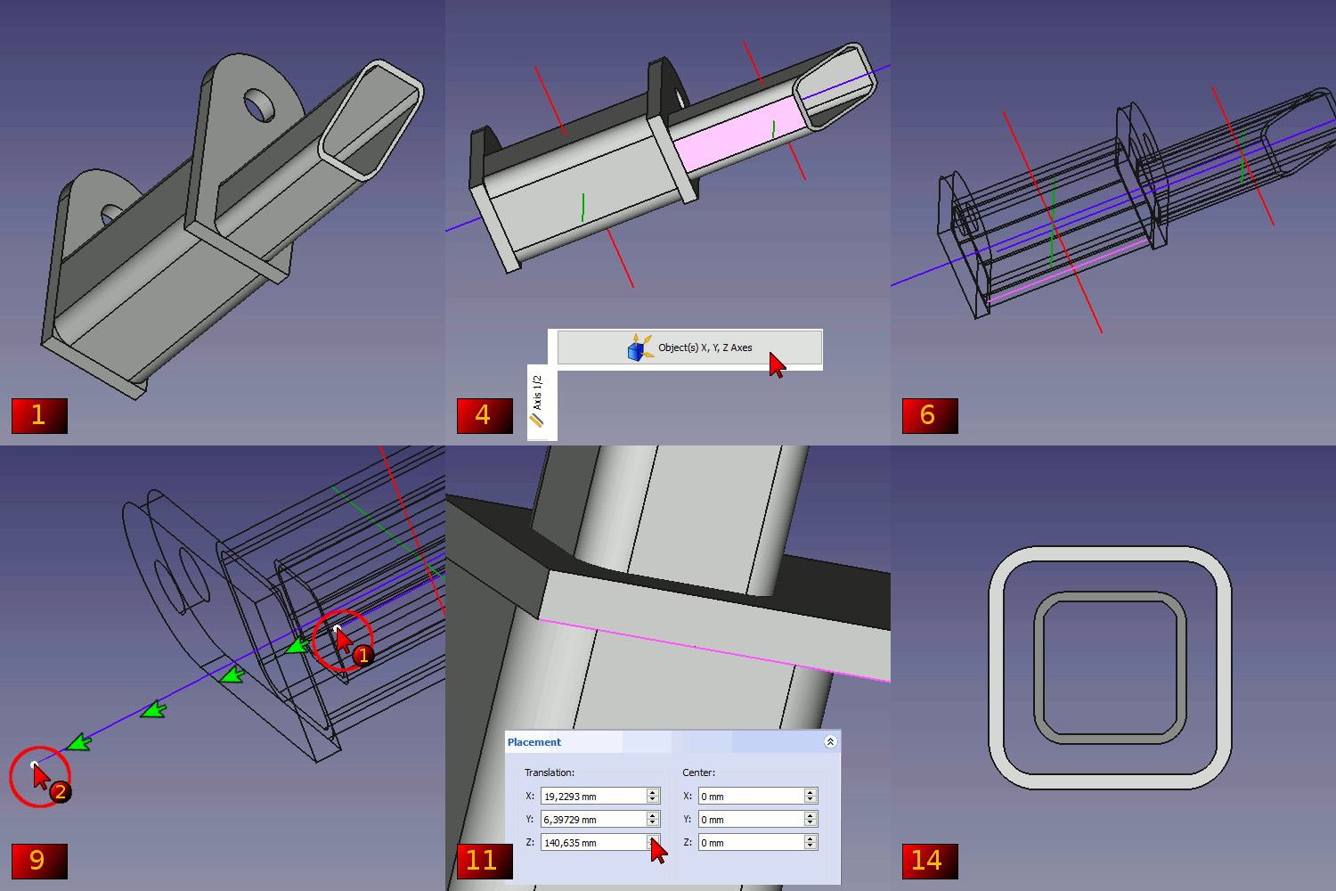
| Wie eine Beschränkung zwischen zwei nicht zylindrischen Teilen herstellen. 1 : Das zu ändernde Originalobjekt. 2 : Zielmitte zweier Vierkantrohre. 3 : Wähle das erste Objekt und klicke im Menü Achse 1/2 auf "Objekt(e)" X, Y, Z Axes. 4 : Gleiche Vorgehensweise für das zweite Objekt. 5 : Klicke auf Schaltfläche Draw style und auf "Wireframe", 6 : zur Verdeutlichung der Ansicht. 7 : Wähle das zu zentrierende Objekt und seine erstellte Achse. 8 : Klicke die Schaltfläche Draft Move 9 : und wähle die erste Achse, die auf der zweiten Achse verschoben werden soll. 10 : Normalansicht mit der Taste Zeichenstil und auf Originalwiederherstellen. 11 : Klicke das erste verschobene Objekt und korrigiere die Position mit "Comboansicht > Daten > Positionierung". 12 : Wähle das von WorkFeature erstellte Objekt (Contener Achse) aus und lösche es. 13 : Das Objekt verschwindet. 14 : Das Ergebnis. |
Rotationsobjekt
-
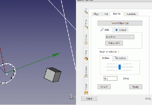
Click the image for see the animation.
Ebene auf Flächentangente
-
Click the image for see the animation.
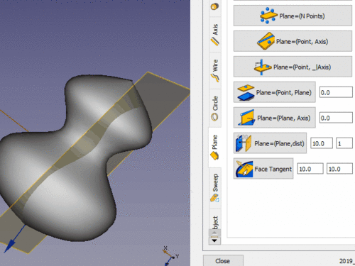
Click the object, click the Face tangent button, click the point on face for create the plane.
Verweise
Die Forumsdiskussion MACRO:Work Feature 2014_12
Externe Arbeitsbereiche
FreeCAD Arbeitsbereiche sind einfach in Python zu programmieren, daher gibt es viele Leute, die zusätzliche Arbeitsbereiche außerhalb der FreeCAD Hauptentwickler entwickeln.
Die Externe Arbeitsbereiche Seite enthält einige Informationen und Tutorien zu einigen von ihnen, und das FreeCAD Erweiterungen Projekt zielt darauf ab, sie zu sammeln und einfach aus FreeCAD heraus zu installieren.
Neue Arbeitsbereiche sind in der Entwicklung, bleib dran!
Neueste Version
Symbole :
Quellen :
Auf github : /github.com/Rentlau/WorkFeature-WB.git
Datum 2019-05-01 (YYYY-MM-DD)
20/01/2019
08/03/2015 : WF_2015_03_08 - Kreisschnitt hinzugefügt - Sind parallel, Sind senkrecht, Sind koplanar hinzugefügt
17/02/2015 : WF_2015_02_17 - Reiter Kreis und Ellipse hinzugefügt - Reiter Schneiden hinzugefügt
25/01/2015 : WF_2015_01_25.zip Objekt Zylinder Würfel hinzugefügt
18/01/2015 : WF_2015_01_18.tar.gz Ebene und Fläche zur Ansicht hinzufügen
28/12/2014 : WorkFeatures_2014_12_28.zip
27/12/2014 : WF_2014_12_27.zip
- Erste Schritte
- Installation: Herunterladen, Windows, Linux, Mac, Zusätzlicher Komponenten, Docker, AppImage, Ubuntu Snap
- Grundlagen: Über FreeCAD, Graphische Oberfläche, Mausbedienung, Auswahlmethoden, Objektname, Programmeinstellungen, Arbeitsbereiche, Dokumentstruktur, Objekteigenschaften, Hilf FreeCAD, Spende
- Hilfe: Tutorien, Video Tutorien
- Arbeitsbereiche: Std Base, Arch, Assembly, CAM, Draft, FEM, Inspection, Mesh, OpenSCAD, Part, PartDesign, Points, Reverse Engineering, Robot, Sketcher, Spreadsheet, Surface, TechDraw, Test Framework

