Tutorial custom placing of windows and doors/de: Difference between revisions
(Created page with "{{Caption|align=center|Fenster-Skizze, verschoben zur gewünschten Position auf der Wand}}") |
(Created page with "{{Caption|align=center|Benannte Einschränkungen der Skizze, welche verändert werden können, ohne die Skizze zu öffnen}}") |
||
| Line 107: | Line 107: | ||
[[Image:06_T02_window_sketch_properties_constraints.png|600px|center]] |
[[Image:06_T02_window_sketch_properties_constraints.png|600px|center]] |
||
{{Caption|align=center| |
{{Caption|align=center|Benannte Einschränkungen der Skizze, welche verändert werden können, ohne die Skizze zu öffnen}} |
||
11. Change back to the [[Arch Workbench]] and, with the new {{incode|Sketch002}} selected, use [[Arch Window]]. A window will be created, and will make a hole in the wall. The window is made from a custom sketch, and not from a preset, so it needs to be edited in order to correctly display its components, that is, the fixed frame, the inner frame, and the glass panel. |
11. Change back to the [[Arch Workbench]] and, with the new {{incode|Sketch002}} selected, use [[Arch Window]]. A window will be created, and will make a hole in the wall. The window is made from a custom sketch, and not from a preset, so it needs to be edited in order to correctly display its components, that is, the fixed frame, the inner frame, and the glass panel. |
||
Revision as of 20:51, 14 February 2020
| Thema |
|---|
| Architektur |
| Niveau |
| fortgeschrittener Anfänger |
| Zeit zum Abschluss |
| 60 Minuten |
| Autoren |
| vocx |
| FreeCAD-Version |
| 0.18 oder höher |
| Beispieldateien |
| keine |
| Siehe auch |
| None |
Einleitung
Dieses Tutorial zeigt, wie man benutzerdefinierte Fenster und Türen in einem Gebäudemodell platziert. Es verwendet die Arbeitsbereiche Entwurf (Draft), Architektur (Arch) und Skizze (Sketcher).
Häufig benutzte Werkzeuge sind: Draft:Raster (Grid), Draft:Fang (Snap), Draft: Linienwerkzeug (Wire), Arch:Wand (Wall), Arch:Fenster (Window) und Sketcher:Neue Skizze (NewSketch). Der Anwender sollte mit der Einschränkung von Skizzen vertraut sein.
Dieses Tutorial wurde inspiriert von den Tutorials von jpg87, welche in folgenden FreeCAD-Foren gepostet wurden:
Einrichtung
1. Öffne FreeCAD, erstelle ein neues, leeres Dokument und wechsel zum Architektur-Arbeitsbereich.
2. Stelle sicher, dass Deine Einheiten im Menü Bearbeiten → Einstellungen → Allgemein → Einheiten korrekt eingestellt sind. Zum Beispiel ist MKS (m/kg/s/Grad) gut geeignet, um mit den Abständen in einem typischen Gebäude umzugehen; setze außerdem die Anzahl der Nachkommastellen auf 4, um auch die kleinsten Teile eines Meters zu berücksichtigen.
3. Benutze die Schaltfläche Entwurfsraster ein-/ausschalten, um ein Raster mit ausreichender Auflösung einzublenden. Das Erscheinungsbild des Rasters kannst Du im Menü Bearbeiten → Einstellungen → Draft → Raster und einrasten → Raster ändern. Setze "Hauptlinien alle" auf
20, "Rasterabstand" auf 50 mm und "Rastergröße" auf 1000 Linien (das Raster wird damit eine Fläche von 50m x 50m abdecken).
4. Zoome im 3D-Ansichtsfenster heraus, wenn Du zu nahe am Raster bist.
Jetzt sind wir bereit, um eine einfache Wand zu erstellen, in welcher wir Fenster und Türen positionieren können.
Wände erstellen
5. Benutze das Draft: Linienwerkzeug, um einen Linienzug zu erstellen. Gehe gegen den Uhrzeigersinn vor.
- 5.1. Erster Punkt bei (0, 4, 0); gib im Dialog ein: 0 m Enter, 4 m Enter, 0 m Enter.
- 5.2. Zweiter Punkt bei (2, 0, 0); gib im Dialog ein: 2 m Enter, 0 m Enter, 0 m Enter.
- 5.3. Ditter Punkt bei (4, 0, 0); gib im Dialog ein: 4 m Enter, 0 m Enter, 0 m Enter.
- 5.4. Vierter Punkt bei (6, 2, 0); gib im Dialog ein: 6 m Enter, 2 m Enter, 0 m Enter.
- 5.4. Fünfter Punkt bei (6, 5, 0); gib im Dialog ein: 6 m Enter, 5 m Enter, 0 m Enter.
- 5.5. Drücke A um den Linienzug zu beenden.
- 5.6. Drücke auf dem Nummernblock 0 um eine isometrische Projektion des Modells zu erhalten.
- Hinweis: Stelle sicher, dass die Relative-Checkbox deaktiviert ist, wenn Du Absolut-Koordinaten eingibst.
- Hinweis 2: Die Punkte können auch mit dem Mauscursor durch Anklicken der Rasterschnittpunkte unter Zuhilfenahme der Draft:Fang-Werkzeugleiste und der Raster-Methode definiert werden.
- Hinweis 3: Du kannst die Konturen auch programmatisch durch Scripting in Python erstellen. Bedenke, dass die meisten Funktionen ihre Eingaben in Millimetern erwarten:
import FreeCAD
import Draft

p = [FreeCAD.Vector(0.0, 4000.0, 0),
FreeCAD.Vector(2000.0, 0.0, 0.0),
FreeCAD.Vector(4000.0, 0.0, 0.0),
FreeCAD.Vector(6000.0, 2000.0, 0.0),
FreeCAD.Vector(6000.0, 5000.0, 0.0)]

w = Draft.makeWire(p, closed=False)
6. Wähle DWire im Modellbaum aus und klicke auf das Arch:Wand-Werkzeug; die Wände werden daraufhin mit einer voreingestellten Breite (Dicke) von 0.2 m und einer Höhe von 3 m erstellt.
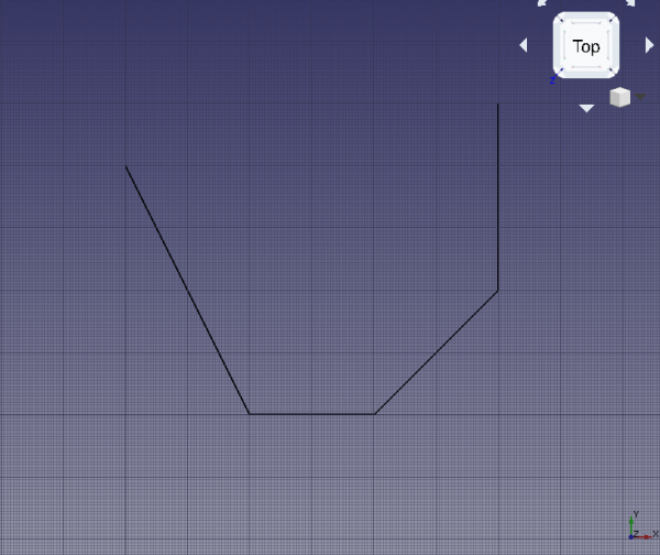
Basis-Linienzug für die Wände
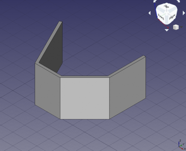
Die aus dem Linienzug konstruierten Wände
vordefinierte Türen und Fenster erstellen
7. Klicke auf das Werkzeug Arch:Fenster, wähle die Voreinstellung (preset) Simple door aus und ändere die Höhe auf 2 m.
- 7.1. Ändere die Fangmethode auf Mittelpunkt und versuche die untere Kante der vorderen Wand auszuwählen. Wenn nötig verdrehe die 3D-Ansicht, um die Kante und nicht die Wandoberfläche anklicken zu können; wenn der Mittelpunkt aktiv ist, klicke um die Tür zu platzieren.
- 7.2. Klicke noch einmal auf das Werkzeug Arch:Fenster und platziere eine weitere Tür, aber diesmal am Mittelpunkt der am weitesten rechts befindlichen Wand; verdrehe dazu die 3D-Ansicht soweit wie nötig.
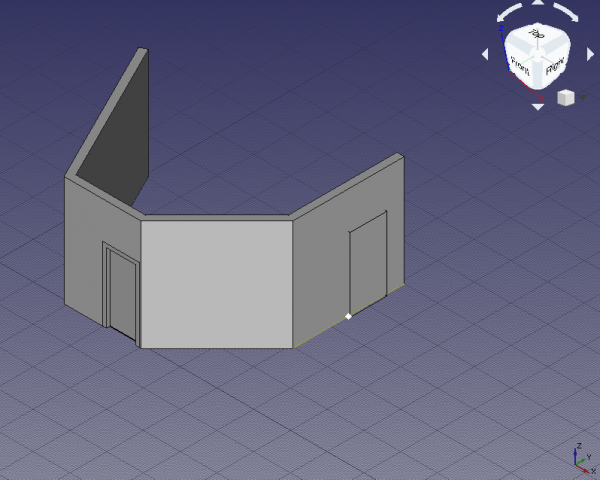
Fangen des Mittelpunktes der unteren Wandkante um die Tür zu platzieren
- Hinweis: Die
Sill height(Brüstungshöhe) ist der Abstand vom Fußboden bis zur unteren Fensterkante. Für Türen ist dieSill heightgewöhnlich 0 m weil Türen normalerweise bis zum Fußboden reichen; andererseits haben Fenster üblicherweise einen Abstand von 0,5 m bis 1,5 m zum Fußboden. Der ParameterSill height(Brüstungshöhe) kann nur während des ursprünglichen Erzeugens eines Fensters oder einer Tür mittels Voreinstellung (preset) eingegeben werden. Ist das Fenster oder die Tür erst einmal eingefügt, lässt sich seine Lage durch Editieren der Eigenschaft DatenPosition[x, y, z]der zugrundeliegenden Skizze modifizieren.
benutzerdefinierte Türen und Fenster erstellen
8. Wechsel zum Sketcher-Arbeitsbereich, wähle den Teil der Wand auf der rechten Seite aus, welcher keine Tür hat. Klicke auf NeueSkizze und wähle FlatFace als Verknüpfungs-Methode. Wenn die vorhandene Geometrie Deine Sicht beeinträchtigt, klicke auf "Schnitt anzeigen", um diese auszublenden.
9. Zeichne eine ausgefallene Skizze, welche 3 geschlossene Linienzüge enthält. Stelle sicher, dass alle Linienzüge komplett beschränkt sind.
- 9.1. Der äußere Linienzug ist der größte und wird die Hauptabmessungen des Fenster-Objektes sowie die Größe der Öffnung beim Einfügen in die Wand definieren. Stelle sicher, dass die Abmessungen passend bezeichnet werden, z.B.
WidthundHeight. Eine Beschränkung definiert auch die Krümmung des äußeren Linienzuges. Gib ihm eine geeignete Bezeichnung, z.B.HeightCurve. - 9.2. Der zweite Linienzug ist vom äußeren versetzt, zusammen definieren beide die Breite des (feststehenden) Fensterrahmens. Benenne den Versatz passend, z.B.
FrameFixedOffset. Er wird für den oberen und beide seitlichen Versätze verwendet. Der untere Versatz bewirkt, wenn auf Null gesetzt, dass der Fensterrahmen den Boden der Öffnung berühren wird - dies kann verwendet werden, um anstelle eines Fensters eine Tür zu modellieren. Gib ihm eine passende Bezeichnung, z.B.FrameFixedBottom. - 9.3. Der dritte, ganz innerste Linienzug ist versetzt zum zweiten und definiert mit diesem zusammen die Breite des Fensterflügel-Rahmens. Der innerste Linienzug definiert gleichzeitig die Größe der Scheibe. Gib auch diesen Versätzen aussagekräftigen Bezeichnungen, z.B.
FrameInnerOffsetundFrameInnerBottom. - 9.4. Um erfolgreich eine Skizze zu erstellen, verwende horizontale und vertikale Beschränkungen für die geraden Seiten. Verwende Konstruktions-(Hilfs-)geometrie und tangentiale Beschränkungen, um die oberen Kreisbögen korrekt zu plazieren. Wenn das Fenster wie im vorliegenden Fall symmetrisch ist, erwäge die Verwendung von Gleichheits-, Symmetrie- und Punkt-auf-Objekt-Beschränkungen, wenn es sinnvoll ist.

Beschränkungen für die äußeren Linienzüge der Skizze, welche das Fenster beschreiben
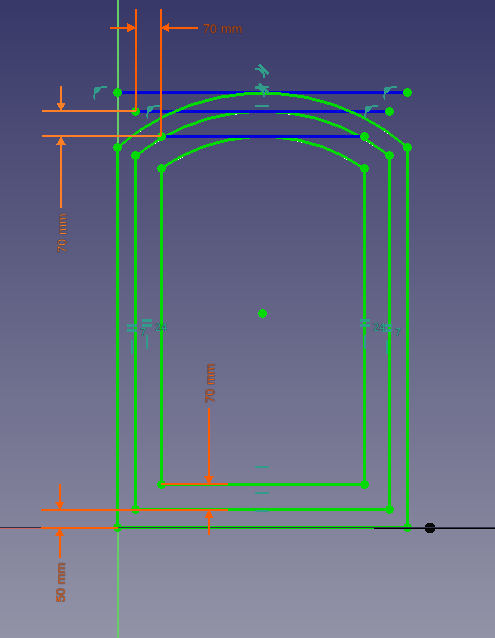
Beschränkungen für die inneren Linienzüge des Skizze, welche das Fenster beschreiben
10. Wenn die Skizze vollständig eingeschränkt ist, drücke Schließen um die Skizze zu verlassen (Skizze beenden).
- 10.1. Da während des Anlegens der Skizze die Oberfläche der Wand ausgewählt war, ist die Skizze ebenengleich zu dieser Wandoberfläche. Allerdings kann sie auch in der falschen Lage, von der Wand weg, sein. Wenn dies der Fall ist, passe die DatenPosition mittels DatenAttachment Offset an. Setze DatenPosition auf
[4 m, 1 m, 0 m], so dass die Skizze zentriert in der Wand sowie 1m über dem Fußboden liegt. - 10.2. Du kannst die benannten Einschränkungen unter DatenConstraints einsehen. Die Werte können verändert werden, die Skizze ändert sofort ihre entsprechenden Abmessungen.
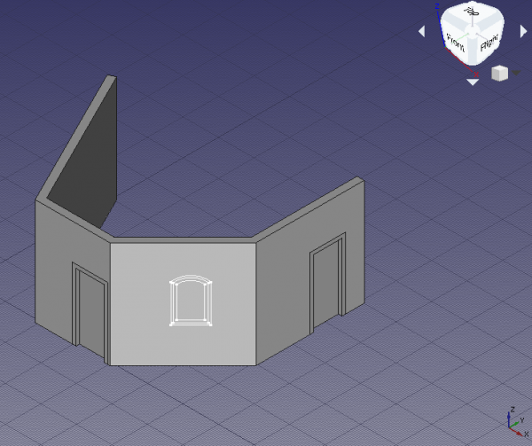
Fenster-Skizze, verschoben zur gewünschten Position auf der Wand
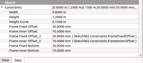
Benannte Einschränkungen der Skizze, welche verändert werden können, ohne die Skizze zu öffnen
11. Change back to the Arch Workbench and, with the new Sketch002 selected, use Arch Window. A window will be created, and will make a hole in the wall. The window is made from a custom sketch, and not from a preset, so it needs to be edited in order to correctly display its components, that is, the fixed frame, the inner frame, and the glass panel.
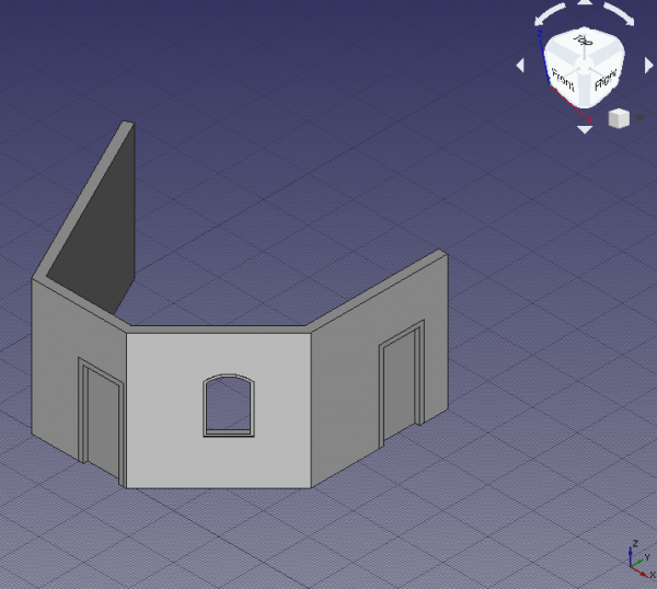
Custom window created from the sketch; it still doesn't have a proper frame, nor glass
Setting up the custom window
12. In the tree view select Sketch002 underlying Window, and press Space, or change the property AnsichtVisibility to true.
13. Double click Window in the tree view to start editing it.
- 13.1. Inside the
Window elementsdialog there are two panes,WiresandComponents. There are three wires,Wire0,Wire1, andWire2, and one component,Default. The wires refer to the closed loops that were drawn in the sketch; the components define the areas in the sketch that will be extruded to create frame or glass panels with real thicknesses; these areas are delimited by the wires. A window created from a preset already has two components,OuterFrameandGlass. The custom window needs to be edited to have a similar structure.
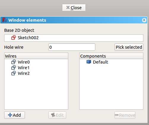
Dialog to edit a window or a door
- 13.2. Click on
Default, and click the Remove button to eliminate it.
- 13.3. Click Add; this shows the properties of a new component like
Name,Type,Wires,Thickness,Offset,Hinge, andOpening mode. Give a name, such asOuterFrame, chooseFrameforType, and click onWire0and thenWire1; they should highlight in the 3D viewport. Add a small value forThickness,15 mm, and check the checkbox to add the default value. This default value is the length assigned to the DatenFrame property; a similar default can be assigned to the DatenOffset property. Click the +Create/update component button to finish editing the component.
- 13.4. Click Add; give another name, such as
InnerFrame, chooseFrameforType, and click onWire1and thenWire2. Add a sensibleThickness,60 mm, andOffset,15 mm. Then click the +Create/update component button.
- 13.5. Click Add; give another name, such as
Glass, chooseGlass panelforType, and click onWire2. Add a sensibleThickness,10 mm, andOffset,40 mm. Then click the +Create/update component button. If any of the three components needs to be modified, select it and press Edit; modifications are only saved after pressing the +Create/update component button.
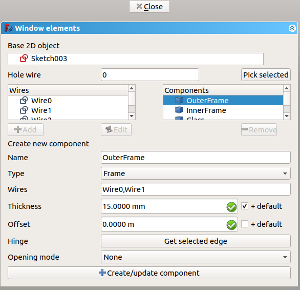
Editing a previously defined component of a window or a door
- 13.6. If everything is set, click Close to finish editing the window. The sketch may become hidden again, but the window will show distinct solid elements for the
OuterFrame, theInnerFrame, and theGlass. Give a value of100 mmto DatenFrame to assign a default thickness, which will be added to the value specified in theOuterFramecomponent.
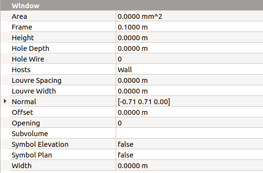
Property view of the window to add default Frame length, Offset length, and other options
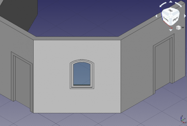
Finished window with appropriate components embedded in the wall
Duplicating the custom window
14. In the tree view, select Window and its underlying Sketch002. Then go to Edit → Duplicate selection, and answer No if asked to duplicate unselected dependencies. A new Window001 and Sketch003 will appear in the same position as the original elements.
15. Select the new Sketch003. Go to the DatenMap Mode property, and click on the ellipsis next to the FlatFace value. In the 3D viewport select the left side of the wall which doesn't have any element; rotate the standard view as necessary. Change the Attachment offset to [-1 m, 0 m, 0 m] to center the window, and click OK. The sketch and the window should appear in a new position.
- Note: the attachment operation can also be performed by changing to the Part Workbench, and then using the menu Part → Attachment.
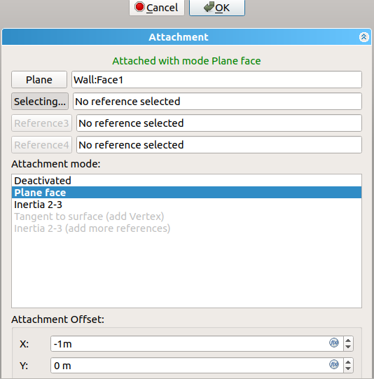
Dialog to edit the attachment plane of the sketch
16. You may adjust the dimensions of the new window by changing the named parameters in Sketch003 under DatenConstraints, for example, set Height to 2 m, and Frame Fixed Bottom to 0 m. Then press Ctrl+R to recompute the model. If the wall doesn't show a bigger hole for the new window, select the wall in the tree view, right click and choose Mark to recompute, then press Ctrl+R again.
17. These operations have changed the position of the new window, but the opening in the wall doesn't look correct. It is slanted, that is, the hole is not perpendicular to the face of the wall, and it may even cut other parts of the wall. The problem is that Window001 has retained the DatenNormal information of the original Window.
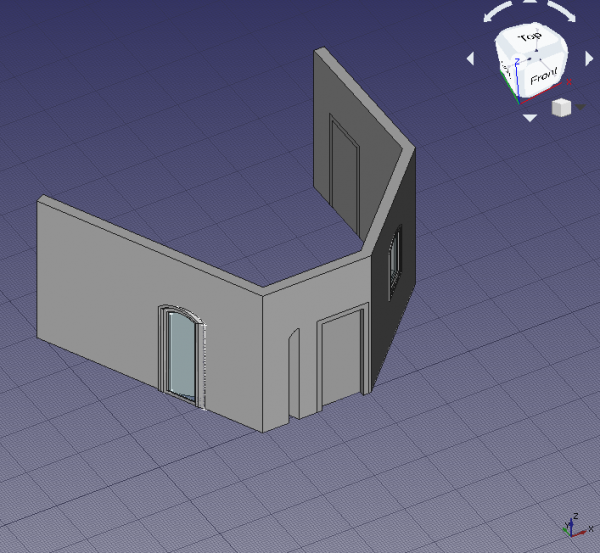
Incorrect opening in the wall due to bad Normal of the window
Normals of doors and windows
18. Each Arch Window object controls the extrusion of its body and the opening that is created in its host wall by means of the DatenNormal.
The normal is a vector [x, y, z] that indicates a direction perpedicular to a wall. When a window or door preset is created with the Arch Window tool directly over an Arch Wall, the normal is automatically calculated, and the resulting window or door is correctly aligned; the first two objects, Door and Door001, were created in this way.
In similar way, when a sketch is created by selecting a planar surface, it is oriented on this plane. Then when the Arch Window tool is used, the window will use as normal the perpendicular direction to the sketch. This was the case with the third object, the custom Window.
If the window already exists and needs to be moved, as was the case with the duplicated Window001 object, the sketch needs to be remapped to another plane; doing this moves both the sketch and the window, but the latter doesn't automatically update its normal, so it has incorrect extrusion information. The normal needs to be calculated manually and written to DatenNormal.
The three values of the normal vector are calculated as following.
x = -sin(angle)
y = cos(angle)
z = 0
Where angle is the angle of the local Z axis of the sketch with respect to the global Y axis.
When a sketch is created, it always has two axes, a local X (red) and a local Y (green). If the sketch is mapped to the global XY working plane, then these axes are aligned; but if the sketch is mapped on the global XZ or global YZ planes, as is common with windows and doors (the sketches are "standing up"), then the local Z (blue) forms an angle with the global Y axis; this angle varies from -180 to 180 degrees. The angle is considered positive if it opens counterclockwise, and it is negative if it opens clockwise, starting from the global Y axis.
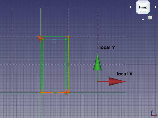
Local coordinates of a sketch that is "standing up", that is, mapped to the global XZ plane
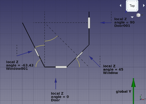
Intended directions of the normals for each door and window
If we look at the geometry created so far, we see the following normals.
Door- The local Z is aligned with the global Y, therefore, the
angleis zero. The normal vector is
x = -sin(0) = 0
y = cos(0) = 1
z = 0
or DatenNormal is [0, 1, 0].
Door001- The local Z is rotated 90 degrees from the global Y, therefore, the
angleis 90 (positive, because it opens counterclockwise). The normal vector is
x = -sin(90) = -1
y = cos(90) = 0
z = 0
or DatenNormal is [-1, 0, 0].
Window- The local Z is rotated 45 degrees from the global Y, therefore, the
angleis 45 (positive, because it opens counterclockwise). The normal vector is
x = -sin(45) = -0.7071
y = cos(45) = 0.7071
z = 0
or DatenNormal is [-0.7071, 0.7071, 0].
Window001- The local Z direction is found by using the Draft Dimension tool and measuring the angle that the wall trace (
Wire) makes with the global Y axis, or any line aligned to it. This angle is26.57; the desired angle is the complement to this, so90 - 26.57 = 63.43.
This means the local Z axis is rotated 63.43 degrees from the global Y, therefore, the angle is -63.46 (negative, because it opens clockwise). The normal vector is
x = -sin(-63.43) = 0.8943
y = cos(-63.43) = 0.4472
z = 0
Therefore DatenNormal should be changed to [0.8943, 0.4472, 0].
After doing these changes, recompute the model with Ctrl+R. If the wall doesn't update the hole, select it in the tree view, right click and choose Mark to recompute, then press Ctrl+R again.
19. The orientation of the extrusion of the window is resolved, together with the opening in the wall.
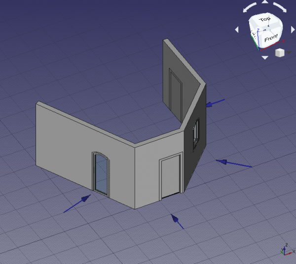
Correct opening in the wall due to proper Normal of the window
Final remarks
20. As demonstrated, the initial placement of the Arch Window is very important. The user should either
- use the Arch Window tool to insert and automatically align a preset to a wall, or
- map a sketch to the desired wall, and build the window after that.
If a window already exists, and it needs to be moved, the supporting sketch should be remapped to a new plane, and the DatenNormal of the window needs to be recalculated.
The new normal direction can be obtained by measuring the angle of the new wall with respect to the global Y axis, considering whether this angle is positive (counterclockwise) or negative (clockwise), and using a simple formula.
x = -sin(angle)
y = cos(angle)
z = 0
To confirm that the operations are correct, the absolute magnitude of the normal vector should be one. That is,
abs(N) = 1 = sqrt(x^2 + y^2 + z^2)
abs(N) = 1 = sqrt(sin^2(angle) + cos^2(angle) + z^2)
- Erste Schritte
- Installation: Herunterladen, Windows, Linux, Mac, Zusätzlicher Komponenten, Docker, AppImage, Ubuntu Snap
- Grundlagen: Über FreeCAD, Graphische Oberfläche, Mausbedienung, Auswahlmethoden, Objektname, Programmeinstellungen, Arbeitsbereiche, Dokumentstruktur, Objekteigenschaften, Hilf FreeCAD, Spende
- Hilfe: Tutorien, Video Tutorien
- Arbeitsbereiche: Std Base, Arch, Assembly, CAM, Draft, FEM, Inspection, Mesh, OpenSCAD, Part, PartDesign, Points, Reverse Engineering, Robot, Sketcher, Spreadsheet, Surface, TechDraw, Test Framework