Podręcznik:Tworzenie i obróbka geometrii
- Słowo wstępne
- Odkrywamy FreeCAD
- Praca z FreeCAD
- Skrypty środowiska Python
- Społeczność
W poprzednich rozdziałach dowiedzieliśmy się o różnych środowiskach pracy programu FreeCAD oraz o tym, jak każde z nich stosuje swoje własne narzędzia i typy geometrii. Ta sama koncepcja obowiązuje przy pracy z kodem Pythona.
Zauważyliśmy również, że zdecydowana większość środowisk pracy FreeCAD zależy od bardzo fundamentalnego elementu: Środowiska pracy Part. W rzeczywistości, wiele innych środowisk pracy, takich jak Draft i Arch, wykonuje dokładnie to, co zrobimy w tym rozdziale: używa kodu Python do tworzenia i manipulowania geometrią Części.
So the first thing we need to do to work with Part geometry, is to do the Python equivalent to switching to the Part Workbench: import the Part module:
import Part
Take a minute to explore the contents of the Part module, by typing Part. and browsing through the different methods available. The Part module offers several convenience functions such as makeBox, makeCircle, etc... which will instantly build an object for you. Try this, for example:
Part.makeBox(3,5,7)
When you press Enter after typing the line above, nothing will appear in the 3D view, but something like this will be printed on the Python Console:
<Solid object at 0x5f43600>
This is where an important concept takes place. What we created here is a Part Shape. It is not a FreeCAD document object (yet). In FreeCAD, objects and their geometry are independent. Think of a FreeCAD document object as a container, that will host a shape. Parametric objects will also have properties such as Length and Width, and will recalculate their Shape on-the-fly, whenever one of the properties changes. What we did here is calculate a shape manually.
We can now easily create a "generic" document object in the current document (make sure you have at least one new document open), and give it a box shape like the one we just made:
boxShape = Part.makeBox(3,5,7)
 myObj = FreeCAD.ActiveDocument.addObject("Part::Feature","MyNewBox")
 myObj.Shape = boxShape
 FreeCAD.ActiveDocument.recompute()
Note how we handled myObj.Shape , notice that it is done exactly like we did it in the previous chapter, when we changed other properties of an object, such as box.Height = 5 . In fact, Shape is also a property, just like Height. Only it takes a Part Shape, not a number. In the next chapter we will have a better look at how these parametric objects are constructed.
For now, let's explore our Part Shapes in more detail. At the end of the chapter about traditional modeling with the Part Workbench we showed a table that explains how Part Shapes are constructed, and their different components (Vertices, edges, faces, etc). The exact same components exist here and can be retrieved from Python. Part Shapes always have the following attributes: Vertexes, Edges, Wires, Faces, Shells and Solids. All of them are lists, that can contain any number of elements or be empty:
print(boxShape.Vertexes)
 print(boxShape.Edges)
 print(boxShape.Wires)
 print(boxShape.Faces)
 print(boxShape.Shells)
 print(boxShape.Solids)
For example, let's find the area of each face of our box shape above:
for f in boxShape.Faces:
   print(f.Area)
Or, for each edge, its start point and end point:
for e in boxShape.Edges:
   print("New edge")
   print("Start point:")
   print(e.Vertexes[0].Point)
   print("End point:")
   print(e.Vertexes[1].Point)
As you see, if our boxShape has a "Vertexes" attribute, each Edge of the boxShape also has a "Vertexes" attribute. As we can expect, the boxShape will have 8 vertices, while the edge will only have 2, which are both part of the list of 8.
We can always check what is the type of a shape:
print(boxShape.ShapeType)
 print(boxShape.Faces[0].ShapeType)
 print(boxShape.Vertexes[2].ShapeType)
So to resume the topic of Part Shapes: Everything starts with Vertices. With one or two vertices, you form an Edge (full circles have only one vertex). With one or more Edges, you form a Wire. With one or more closed Wires, you form a Face (the additional Wires become "holes" in the Face). With one or more Faces, you form a Shell. When a Shell is fully closed (watertight), you can form a Solid from it. And finally, you can join any number of Shapes of any types together, which is then called a Compound.
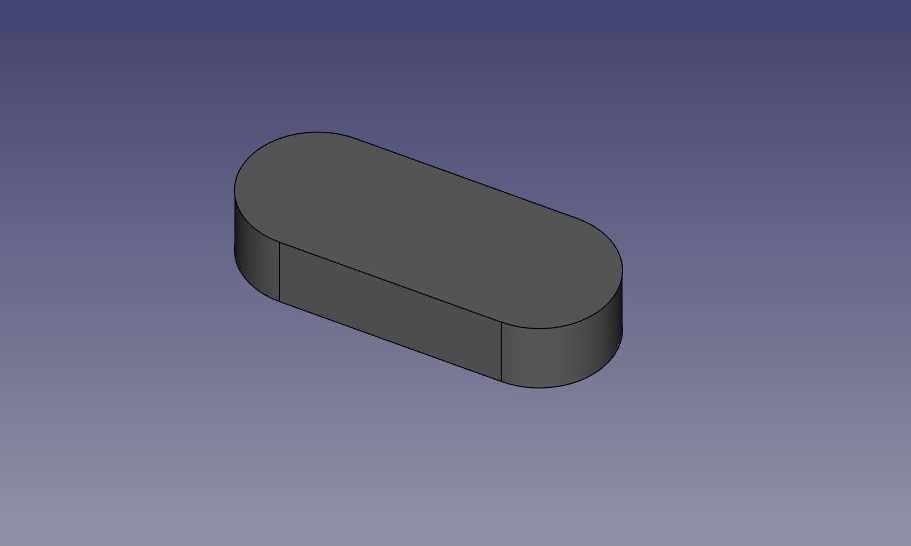
We can now try creating complex shapes from scratch, by constructing all their components one by one. For example, let's try to create a volume like this:
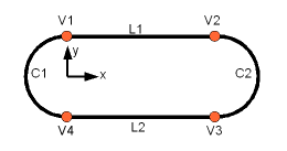
We will start by creating a planar shape like this:
First, let's create the four base points:
V1 = FreeCAD.Vector(0,10,0)
 V2 = FreeCAD.Vector(30,10,0)
 V3 = FreeCAD.Vector(30,-10,0)
 V4 = FreeCAD.Vector(0,-10,0)
Then we can create the two linear segments:
L1 = Part.LineSegment(V1,V2)
L2 = Part.LineSegment(V4,V3)
Zauważ, że nie musieliśmy tworzyć wierzchołków. Mogliśmy natychmiast stworzyć Part.LineSegmenty za pomocą FreeCAD Vectors. To dlatego, że tutaj nie stworzyliśmy jeszcze Krawędzi. Part.LineSegment (jak również Part.Circle, Part.Arc, Part.Ellipse czy Part.BSpline) nie tworzy krawędzi, ale raczej bazową geometrię, na której zostanie utworzony obiekt Edge. Krawędzie są zawsze tworzone z takiej geometrii bazowej, która jest zapisana w atrybucie Curve. Więc jeśli masz krawędzie, to zrób to:
print(Edge.Curve)
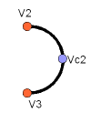
pokaże ci, jaki to rodzaj obiekty Edge, tzn. czy jest oparty na linii, łuku, itd... Ale wróćmy do naszego ćwiczenia, i zbudujmy segmenty łuku. Do tego będziemy potrzebowali trzeciego punktu, więc możemy użyć wygodnego Part.Arc, który pobiera 3 punkty:
VC1 = FreeCAD.Vector(-10,0,0)
 C1 = Part.Arc(V1,VC1,V4)
 VC2 = FreeCAD.Vector(40,0,0)
 C2 = Part.Arc(V2,VC2,V3)
Teraz mamy dwie linie (L1 i L2) i dwa łuki (C1 i C2). Musimy zamienić je na krawędzie:
E1 = Part.Edge(L1)
 E2 = Part.Edge(L2)
 E3 = Part.Edge(C1)
 E4 = Part.Edge(C2)
Alternatywnie, geometrie bazowe mają również funkcję toShape(), która robi dokładnie to samo:
E1 = L1.toShape()
 E2 = L2.toShape()
 ...
Kiedy już będziemy mieli serię krawędzi, możemy teraz stworzyć obwiednię, podając jej listę krawędzi. Musimy zadbać o porządek.
W = Part.Wire([E1,E4,E2,E3])
I możemy sprawdzić, czy nasza obwiednia została prawidłowo wykonana, i czy jest prawidłowo zamknięta:
print( W.isClosed() )
Który wydrukuje True lub False. Aby wykonać powierzchnię, potrzebujemy zamkniętej obwiedni, więc zawsze warto to sprawdzić przed wykonaniem powierzchni. Teraz możemy stworzyć taką powierzchnię, nadając jej pojedynczą obwiednię (lub listę obwiedni, jeśli chcemy uzyskać otwory):
F = Part.Face(W)
Potem go wyciągamy:
P = F.extrude(FreeCAD.Vector(0,0,10))
Należy pamiętać, że P jest już bryłą:
print(P.ShapeType)
To dlatego, że kiedy wyciągamy pojedynczą powierzchnię, zawsze otrzymujemy bryłę. Nie miałoby to miejsca, na przykład, gdybyśmy zamiast tego wyciągnęli obwiednię:
S = W.extrude(FreeCAD.Vector(0,0,10))
 print(s.ShapeType)
Co oczywiście da nam pustą powłokę, z brakującą górną i dolną powierzchnią.
Teraz, gdy mamy nasz ostateczny kształt, chcemy go zobaczyć na ekranie! Stwórzmy więc ogólny obiekt, i przypiszmy do niego naszą nową bryłę:
myObj2 = FreeCAD.ActiveDocument.addObject("Part::Feature","My_Strange_Solid")
 myObj2.Shape = P
 FreeCAD.ActiveDocument.recompute()
Alternatywnie, Środowisko pracy Part dostarcza również skrót, który przyspiesza powyższą operację (ale nie możesz wybrać nazwy obiektu):
Part.show(P)
Wszystko to, oraz wiele więcej, zostało szczegółowo wyjaśnione na stronie Skrypty danych topologicznych, wraz z przykładami.
Więcej informacji:
- Tworzenie skryptów FreeCAD: Python, Wprowadzenie do środowiska Python, Poradnik: Tworzenie skryptów Python, Podstawy tworzenia skryptów FreeCAD
- Moduły: Moduły wbudowane, Jednostki miar, Ilość
- Środowiska pracy: Tworzenie Środowiska pracy, Polecenia Gui, Polecenia, Instalacja większej liczby Środowisk pracy
- Siatki i elementy: Skrytpy w Środowisku Siatek, v, Konwerska Mesh na Part, PythonOCC
- Obiekty parametryczne: Obiekty tworzone skryptami, Obsługa obrazu (Ikonka niestandardowa w widoku drzewa)
- Scenegraph: Coin (Inventor) scenegraph, Pivy
- Interfejs graficzny: Stworzenie interfejsu, Kompletne stworzenie interfejsu w środowisku Python (1, 2, 3, 4, 5), PySide, PySide examples początkujący, średniozaawansowany, zaawansowany
- Makrodefinicje: Makrodefinicje, Instalacja makrodefinicji
- Osadzanie programu: Osadzanie programu FreeCAD, Osadzanie GUI FreeCAD
- Pozostałe: Wyrażenia, Wycinki kodu, Funkcja kreślenia linii, Biblioteka matematyczna FreeCAD dla wektorów (deprecated)
- Węzły użytkowników: Centrum użytkownika, Centrum Power użytkowników, Centrum programisty


