Basic Attachment Tutorial/fr: Difference between revisions
2papyblaise (talk | contribs) (Created page with "Cette notion de l'origine étant le point d'attache est importante, elle rend les modes d'attache très flexibles, et peut être un outil puissant dans votre modélisation.") |
2papyblaise (talk | contribs) (Created page with "Il peut être utilisé avec l'ajout de décalages pour positionner avec précision les esquisses sans dépendre de la géométrie générée et de tous les problèmes pouvant...") |
||
| Line 155: | Line 155: | ||
Cette notion de l'origine étant le point d'attache est importante, elle rend les modes d'attache très flexibles, et peut être un outil puissant dans votre modélisation. |
Cette notion de l'origine étant le point d'attache est importante, elle rend les modes d'attache très flexibles, et peut être un outil puissant dans votre modélisation. |
||
Il peut être utilisé avec l'ajout de décalages pour positionner avec précision les esquisses sans dépendre de la géométrie générée et de tous les problèmes pouvant découler de leur utilisation. |
|||
It can be used with the addition of offsets to precisely position sketches without relying on generated geometry and all the problems that may arise from using them. |
|||
FreeCAD tries to predict the attachment mode for you, and filters the modes available for the given selection. |
FreeCAD tries to predict the attachment mode for you, and filters the modes available for the given selection. |
||
Revision as of 14:00, 2 July 2021
| Topic |
|---|
| Attachment |
| Level |
| {{{Level}}} |
| Time to complete |
| 1 heure |
| Authors |
| Bance |
| FreeCAD version |
| V0.17 ou au delà |
| Example files |
| Basic Attachment Tutorial.FCStd |
| See also |
| None |
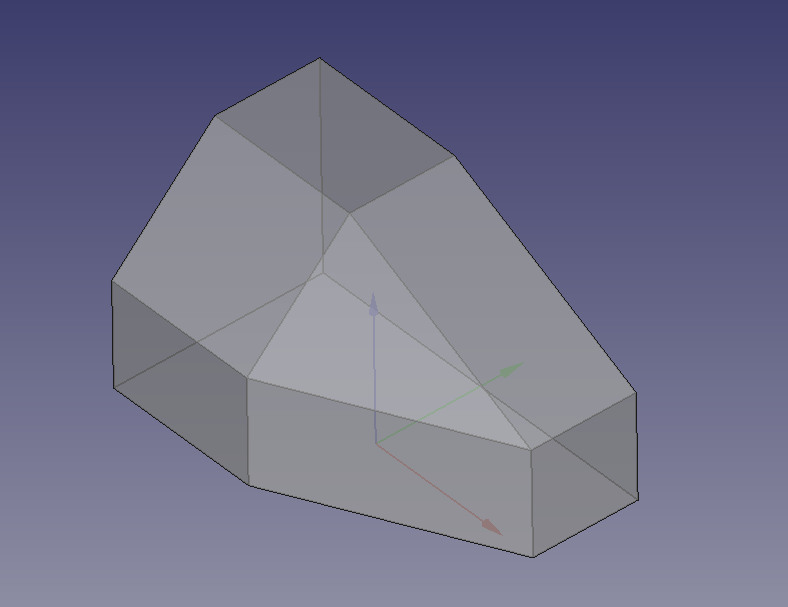
Part:Attachment, Ce tutoriel servira d'introduction à il n'est pas très facile à comprendre , mais utile aux utilisateurs pour plus de détails : questionner des utilisateurs confirmés
Attachment est un utilitaire pour attacher un objet à un autre. Cela lie les propriétés de placement des deux objets, l'objet attaché suivra alors l'original (si son placement est modifié.) L'accent est mis sur l'atelier Part Design et l'attachement d'esquisses à d'autres esquisses, ceci étant une méthode recommandée pour créer des modeles stable . Écrit pour la V0.19, mais devrait être valide pour toute version V0.17 et ultérieure. Cependant, les choses peuvent différer dans certains détails. Le modèle original a été conçu par Md. Aminul Islam et téléchargé à partir d'ici
Prérequis
Avent de demarrer ce tutoriel l'utilisateur doit :-
- avoir la version V0.17 ou supérieure.
- Être à l'aise avec la navigationde vues en 3D 3D view.
- Être capable de contraindre un sketchsketch.
- Avoir un connaissance basique de
Part Design workbench.
- et dans Expressions.
Objectifs
Le but de ce didacticiel est de montrer comment un modèle peut être construit en positionnant des esquisses par rapport à d'autres géométries à l'aide de certains des différents modes d'attachement disponibles.
Bien qu'il soit possible d'utiliser la géométrie solide (Sommets, Arêtes et Faces) pour la géométrie de référence, dans l'intérêt de ce qui est considéré comme une bonne pratique, ce tutoriel s'abstiendra de le faire. Voir Feature Editing pour plus d'explications.
Préliminaires
Avant de commencer, examinons comment nous devrions procéder pour construire ce modèle.
Quel que soit l'angle sous lequel nous le regardons, nous voyons un carré ou un rectangle avec un coin coupé.
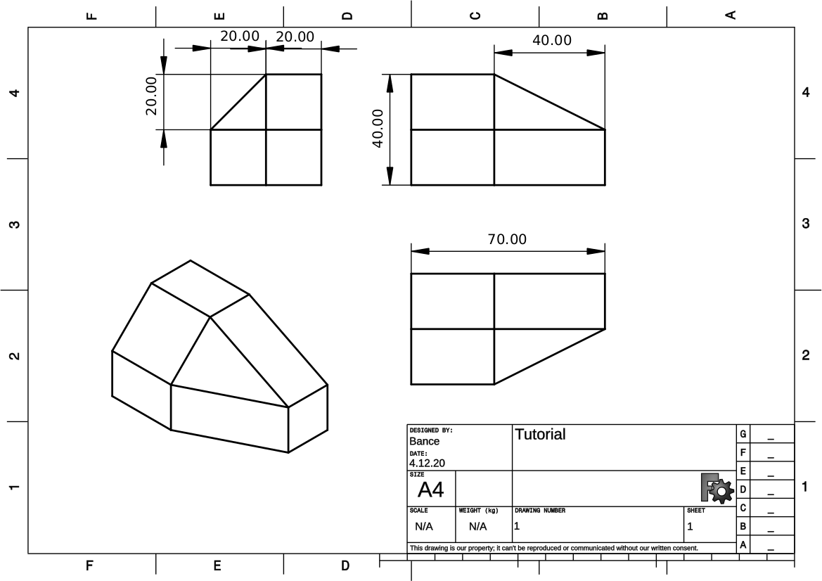
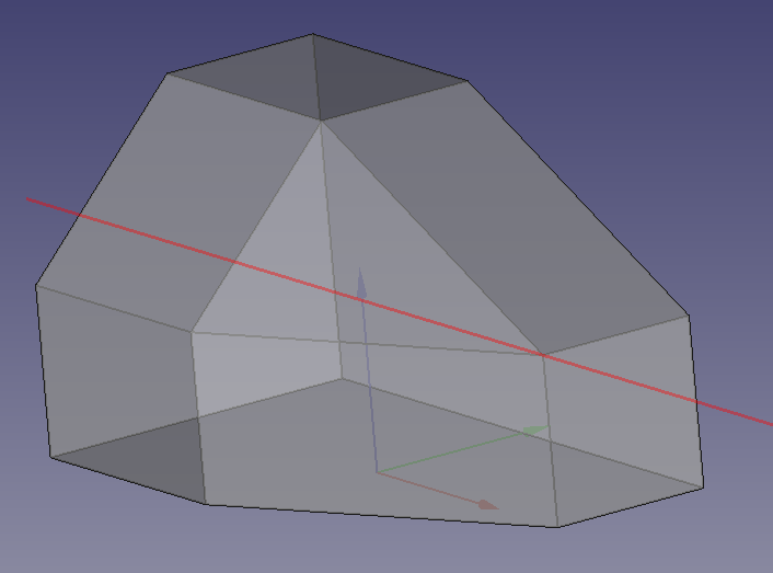
Il existe cependant un axe évident à partir duquel toutes les caractéristiques sont communes.
Il est parfaitement possible de créer une géométrie de données ici et d'y attacher toutes les esquisses. Dans certains modèles, ce serait un choix judicieux, pour les besoins de ce didacticiel, nous nous limiterons aux plans Standard et aux croquis.
Nous pourrions faire un croquis sur n'importe lequel des grands plans. Nous pourrions inclure un coin coupé dans notre croquis de base, mais abandonnons cela et incluons un croquis et une pocket supplémentaire, à des fins d'apprentissage.
Attachment
Nous allons commencer avec un bloc et couper l'excédent.
Basculez vers l'atelier Part Design, ouvrez un nouveau document, créez un corps et une nouvelle esquisse sur le plan XY.
Là, vous venez de faire un attachement. Lorsque vous sélectionnez le plan sur lequel réaliser l'esquisse, c'est en fait ce qui est fait, le dialogue de sélection de plan n'est qu'une version simplifiée du dialogue d'attachement, où tous les décalages sont mis à zéro.
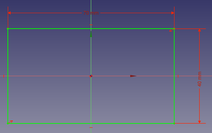
Faire un sketch d'un rectangle centré sur l'origine contraindre avec une longueur (horizontale ) 70mm largeur (verticale) 40mm
Sélectionner le sketch(presser le bouton F2)et le renommer "BaseSketch"
Mode d'attachement
Si nous laissons l'esquisse où elle est, l'exemple serait trop simple, modifions donc la position de l'esquisse en modifiant son décalage de position.
Dans la vue combinée (onglet Données), regardez dans la section Attachment du volet des propriétés, ici nous pouvons voir que BaseSketch a un support de XY_Plane et est attaché avec le mode Flat Face. Regardez plus bas et trouvez la pièce jointe Offset et développez-la en cliquant sur le signe plus à côté.
Faire de même pour le sous-titre Position. Modifier le décalage X à 80 mm et le décalage Y à 90 mm.
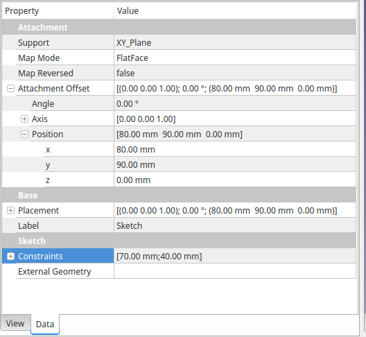
Attachment offset is commonly used in conjunction with expressions to offer a parametric parallel to plane position, eg. positioning a sketch on the top face of a Pad, using a (Pad.Length) expression for Z offset.
L'esquisse peut maintenant être extrudée , supposons que la hauteur du pad doit être la même que la largeur de l'esquisse. Dans la boîte de dialogue Paramètres du pad, sélectionnez la case Longueur, appuyez sur '=' ou sélectionnez l'icône de fonction
et tapez " Sketch.Constraints.width", cette expression doit être résolue en "40 mm", puis cocher Symetric au plan et appuyez sur touche OKOK.
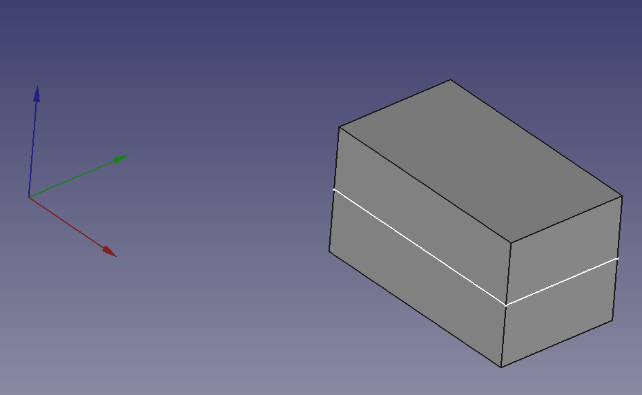
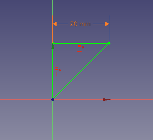
Faisons le prochain croquis, peu importe lequel nous choisissons, mais le plus simple est le triangle isocèle 20x20 qui courre sur toute la longueur du bloc.
Faites un nouveau croquis, choisissez le plan que vous aimez (nous allons quand même changer son attachement.)
Dessinez le triangle, rendez les deux côtés égaux et contraignez la longueur de la même manière que vous l'avez fait pour la longueur du pavé, mais cette fois, faites la formule "Sketch.Constraints.width/2".
Il doit rester deux degrés de liberté, ce sont la position par rapport à l'origine. Fixez l'un des coins à l'origine pour que le croquis ressemble à ceci :-
Changing Attachment
Fermez l'esquisse. Renommez le croquis, appelez-le 'IsocelesSketch'. L'origine de l'esquisse est le point qui sera attaché à l'avenir, il est donc important de choisir comment l'esquisse est contrainte à l'origine. L'origine peut être considérée comme un crochet qui s'accroche à la référence. Nous pouvons ajuster la position de l'esquisse à l'aide de décalages, mais il est préférable de choisir judicieusement en premier lieu.
Nous allons maintenant changer le mode d'attachement de l'esquisse dans notre modèle.
Sélectionnez Pad et rendez-le invisible, et rendez BaseSketch visible. Nous devons voir le BaseSketch et nous voulons masquer le pad afin d'éviter de faire des sélections incorrectes.
La vue 3D doit avoir cette forme
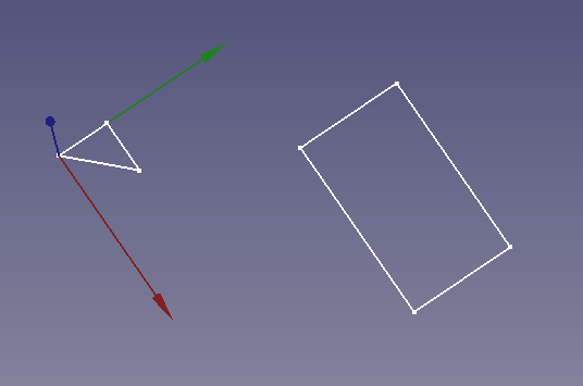
j'ai choisi XY comme plan de construction du triangle isocèle , mais un autre plan peut être choisi
Maintenant sélectionner le sketch Isocèle dans le combo Click sur le cadre MapModeProprièté un bouton aparait
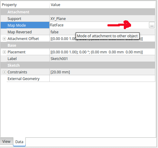
Clicker sur le cadre de valeur , un bouton apparait avec 3 petit points
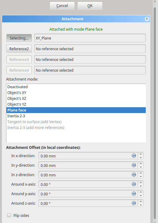
Maintenant on voit l'attachement où le sketch a été créer (dans la sélection du plan )
Le bouton Template:Bouton est en mode de sélection, donc dans la vue 3D, sélectionnez l'un des côtés longs de l'esquisse de base.
L'IsocelesSketch s'attachera à la ligne que vous avez sélectionnée et la fenêtre du mode d'attachement changera pour refléter les modes disponibles.
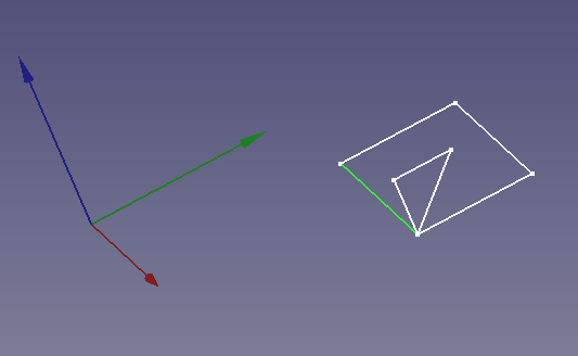
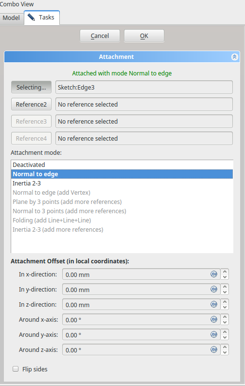
Vous pouvez voir que l'IsocelesSketch a été attaché à la ligne sélectionnée au point que nous avons contraint à l'origine plus tôt.
Cette notion de l'origine étant le point d'attache est importante, elle rend les modes d'attache très flexibles, et peut être un outil puissant dans votre modélisation.
Il peut être utilisé avec l'ajout de décalages pour positionner avec précision les esquisses sans dépendre de la géométrie générée et de tous les problèmes pouvant découler de leur utilisation.
FreeCAD tries to predict the attachment mode for you, and filters the modes available for the given selection.
In this case, the options are "Deactivated," "Normal To Edge" and "Inertia 2-3". Normal To Edge is in bold and is deemed the preferred selection.
The notification area at the top of the dialogue, shows a message in green stating the mode in use.
Grayed out options show that more selections are required in order to activate them.
At this point you could make another selection, and see the difference in modes. Don't forget to change back to "Normal To Edge" mode before continuing with the tutorial.
The IsoscelesSketch is now correctly positioned so confirm and exit the dialogue.
You can now pocket the sketch.
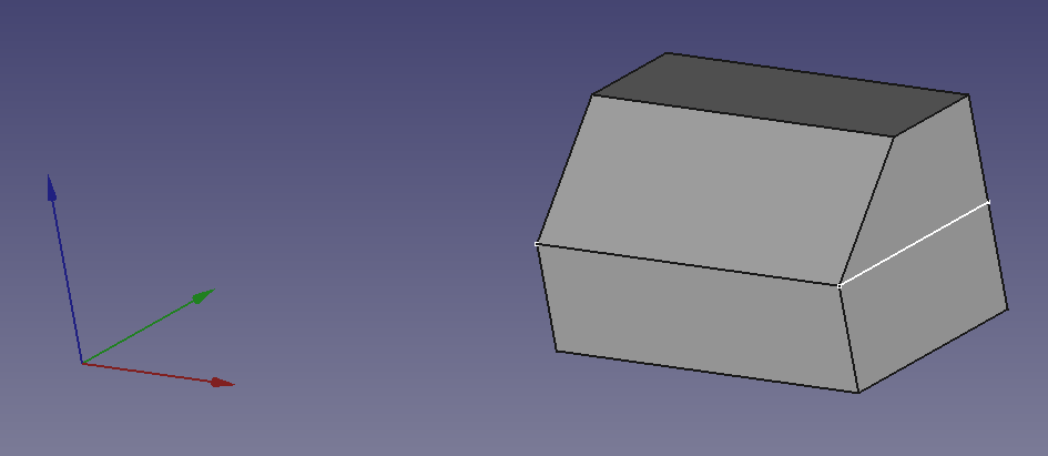
A Step Further
Create the next sketch, the dimensions should be expressions ("Sketch.Constraints.width","Sketch.Constraints.width/2") and it should be constrained to the origin at the vertex adjacent the hypotenuse and its shortest side. (In the empty sketch, if you are familiar with CarbonCopy you can use it to make a copy of the 'IsoscelesSketch' sketch, and edit its parameters to suit.)
Rename the sketch RightAngleTriangleSketch.
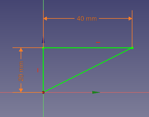
Once again we need to hide the solid, in this case Pocket, and make sure both sketches are visible for selection (leave isoscelesSketch invisible it will just get in the way!).
Select RightAngleTriangleSketch and open its attachment mode dialogue.
Select one of the rectangles short sides as the first reference.
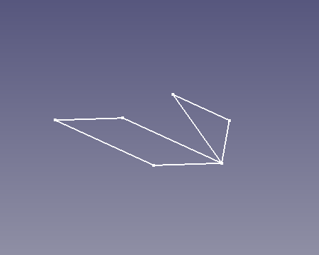
The 3D view should be similar to the picture above. It is not important which end of the line the triangle is attached to (it depends on how the rectangle was drawn!)
If you chose the wrong line, change it now. If the triangle is pointing the wrong way you can correct it by checking the "Flip Sides" checkbox at the bottom of the dialogue (or later on after closing the dialogue it can be changed in the properties data tab by setting "Map Reversed" to "True").
The RightAngleTriangleSketch is now in a position that will give us the correct Geometry after a pocket operation, however we can get a little inventive here, and position the sketch so that it makes it easier for us to attach further geometry later on. We are going to shift our sketch to the middle of the line so that it provides us with a vertex at the top of the corner chamfer.
In the attachment dialogue, we are going to change the attachment mode from "Normal To Edge" to "Inertia 2-3". This will change the position to the centre of the line, it's beyond the scope of this tutorial to describe all the attachment modes, their descriptions can be found at Part Attachment. Suffice to say inertia 2-3 uses the centre of mass and does the job here.
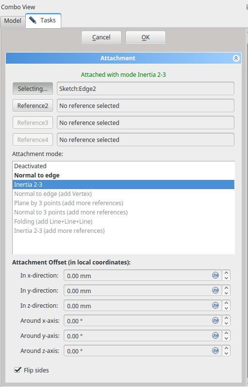
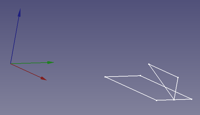
The RightAngleTriangleSketch is now correctly positioned so confirm and exit the dialogue.
You can now pocket the sketch. This time use Symmetric to plane.
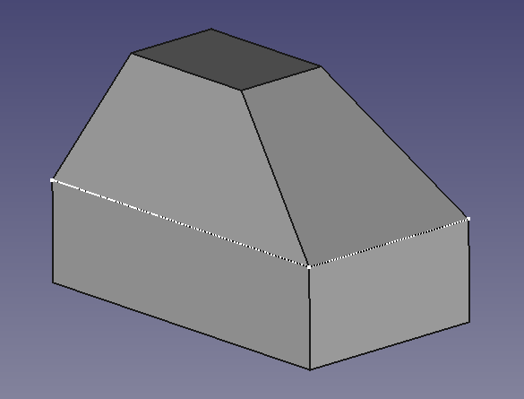
Manipulating Attachment
In general it is better to position our sketches simply with attachment modes. But it is not always possible to position the sketches exactly where we need without modifying the attachment mode in some way.
FreeCAD provides a number of ways to do this.
- Attachment offset, allows positioning relative to the local coordinates of the attachment point. (where the origin of the positioned sketch is attached.)
- Map Path parameter (in the Property data tab with show all enabled) This allows for the positioning along a selected edge.
- Flip Sides/Map Reversed. Effectively mirrors the sketch.
For our final sketch, we will Attach it arbitrarily, and correct its position using the modifiers listed above.
Create the final sketch, the dimensions should be expressions("Sketch.Constraints.width","Sketch.Constraints.width/2") and it should be constrained to the origin at the vertex adjacent the hypotenuse and its shortest side.
Rename the sketch FinalSketch.
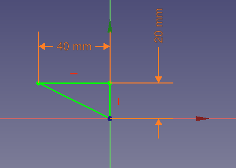
Note that FinalSketch has been constrained to the origin differently. Otherwise we could've used CarbonCopy, but the sketch is only Three lines and five constraints.
Once again we need to hide the solid, in this case Pocket001, and make sure both sketches are visible for selection (BaseSketch and FinalSketch).
Select FinalSketch and open the attachment dialogue, Select one of the rectangles short sides as the first reference.
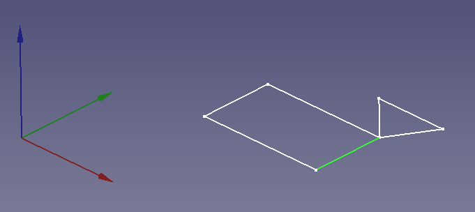
The 3D view should be similar to the picture above. It is not important which end of the line the triangle is attached to (it depends on how the rectangle was drawn!)
Now we need to Flip(mirror) it, translate it through 90° and shift it up to the corner.
At the bottom of the attachment dialogue is a check box labeled 'Flip Sides', check this box.
The FinalSketch mirrors itself.
Now we will translate through 90°. From the illustration FinalSketch above we can see the axis of revolution should be the X axis. In the Wiki this termed Roll. Remember this is relative to the local Coordinate System. Enter 90° in the "around X-axis" box of the attachment offset section of the dialogue.
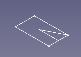
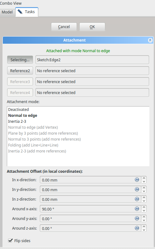
We could use Z-direction offset -- which now corresponds to the opposite Y-direction in the global coordinate system -- to shift FinalSketch to the corner, but I would like to demonstrate another feature.
So let's confirm and close the dialogue for now.
Map Path Parameter
Select FinalSketch and look in the combo view, properties pane in the attachment section, just below the Map Mode property is the Map Path Parameter.
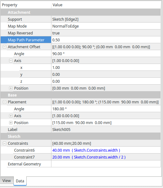
The default setting is 0.0 if we change it to 1 the sketch will map to the other end of the line, and 0.5 gives us half way. Enter 0.5 in the value column.
The combination of 'Normal To Edge' and Map Path Parameter is very useful for positioning sketches for Lofts or Sweeps.
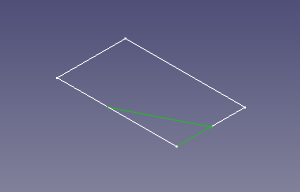
You can now pocket the sketch. Don't forget to use Symmetric to plane.
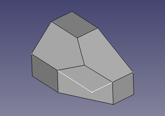
A Different Selection Mode
So far we have seen how to position sketches with attachment modes and offsets, but we could've used Standard planes because the relative positioning was quite simple.
Now we are faced with a more challenging problem, how do we cut away this lump that's left?
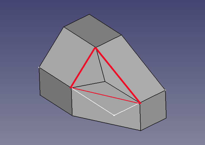
We can sees that there is a plane that passes through the corners of the red triangle, it would be simple if we could just slice it away there.
Well because we were careful with how we positioned our sketches earlier on, we can!
First make the solid invisible, in fact make everything except RightAngleTriangleSketch and FinalSketch invisible.
Now select the three points that form the plane, Don't forget to hold the Ctrl key (CMD on a Mac) while making the selection.
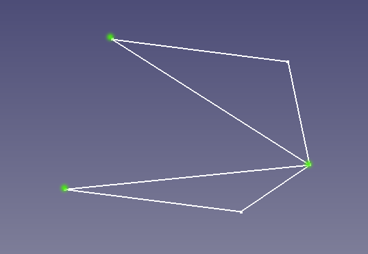
When pressing Create a datum plane, the attachment Dialogue will open showing the three points you selected as references 1-3 and a mode of 'Plane By 3 Points'.
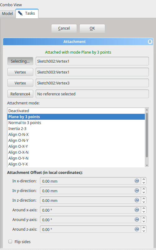
Confirm and close the Dialogue. We could now use the Datum Plane to create a Sketch, but there is no need we can use the plane directly to pocket the excess material away. Make sure the datum Plane is selected, and click on pocket, in the pocket Dialogue select "through all" and "reversed". Close the Dialogue and we are all done.
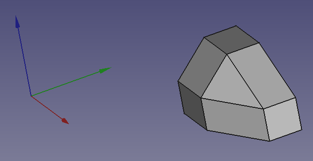
Temporarily attaching to a generated plane
Sometimes it is difficult to work out how to align sketch or datum plane to generated face without actually attaching to it, which as noted above can be problematic. One solution is to attach to the generated geometry and then change the attachment to one of the coordinate planes. FreeCAD will retain the existing position and orientation intact but now reference it to stable planes, thus avoiding the topological renaming problems. However, the cost of doing this that the parametric linkage to the generated geometry is lost. If the underlying model is change, it will not all fall apart as often happens when attaching to generated geometry but attachment will not follow the changes and will need adjusting by repeating the temporary attachment trick.
The previous method is more robust but more abstract and complex to achieve. The temporary attachment trick is quick and easy to implement, more robust than attachment to generated geometry but looses a degree of linkage in the parametric modelling process.
Conclusion
Part Attachment does not guarantee a robust model, the key is to avoid attaching or placing sketches on generated geometry such as faces or edges of pads and pockets.
There are many attachment modes available to users, only the basics are covered here.
One important thing to take away from this tutorial, is the importance of the origin being the 'Hook'. Remember also that orientation is in Local Coordinate System.
Happy Attaching!
- Structure tools: Part, Group
- Helper tools: Create body, Create sketch, Edit sketch, Map sketch to face
- Modeling tools
- Datum tools: Create a datum point, Create a datum line, Create a datum plane, Create a local coordinate system, Create a shape binder, Create a sub-object(s) shape binder, Create a clone
- Additive tools: Pad, Revolution, Additive loft, Additive pipe, Additive helix, Additive box, Additive cylinder, Additive sphere, Additive cone, Additive ellipsoid, Additive torus, Additive prism, Additive wedge
- Subtractive tools: Pocket, Hole, Groove, Subtractive loft, Subtractive pipe, Subtractive helix, Subtractive box, Subtractive cylinder, Subtractive sphere, Subtractive cone, Subtractive ellipsoid, Subtractive torus, Subtractive prism, Subtractive wedge
- Transformation tools: Mirrored, Linear Pattern, Polar Pattern, Create MultiTransform, Scaled
- Dress-up tools: Fillet, Chamfer, Draft, Thickness
- Boolean: Boolean operation
- Extras: Migrate, Sprocket, Involute gear, Shaft design wizard
- Context menu: Set tip, Move object to other body, Move object after other object, Appearance, Color per face
- General: Create sketch, Edit sketch, Map sketch to face, Reorient sketch, Validate sketch, Merge sketches, Mirror sketch, Leave sketch, View sketch, View section, Toggle grid, Toggle snap, Configure rendering order, Stop operation
- Sketcher geometries: Point, Line, Arc, Arc by 3 points, Circle, Circle by 3 points, Ellipse, Ellipse by 3 points, Arc of ellipse, Arc of hyperbola, Arc of parabola, B-spline by control points, Periodic B-spline by control points, B-spline by knots, Periodic B-spline by knots, Polyline, Rectangle, Centered rectangle, Rounded rectangle, Triangle, Square, Pentagon, Hexagon, Heptagon, Octagon, Regular polygon, Slot, Fillet, Corner-preserving fillet, Trim, Extend, Split, External geometry, Carbon copy, Toggle construction geometry
- Sketcher constraints:
- Geometric constraints: Coincident, Point on object, Vertical, Horizontal, Parallel, Perpendicular, Tangent, Equal, Symmetric, Block
- Dimensional constraints: Lock, Horizontal distance, Vertical distance, Distance, Radius or weight, Diameter, Auto radius/diameter, Angle, Refraction (Snell's law)
- Constraint tools: Toggle driving/reference constraint, Activate/deactivate constraint
- Sketcher tools: Select unconstrained DoF, Select associated constraints, Select associated geometry, Select redundant constraints, Select conflicting constraints, Show/hide internal geometry, Select origin, Select horizontal axis, Select vertical axis, Symmetry, Clone, Copy, Move, Rectangular array, Remove axes alignment, Delete all geometry, Delete all constraints
- Sketcher B-spline tools: Show/hide B-spline degree, Show/hide B-spline control polygon, Show/hide B-spline curvature comb, Show/hide B-spline knot multiplicity, Show/hide B-spline control point weight, Convert geometry to B-spline, Increase B-spline degree, Decrease B-spline degree, Increase knot multiplicity, Decrease knot multiplicity, Insert knot, Join curves
- Sketcher virtual space: Switch virtual space
- Additional: Sketcher Dialog, Preferences, Sketcher scripting
- Getting started
- Installation: Download, Windows, Linux, Mac, Additional components, Docker, AppImage, Ubuntu Snap
- Basics: About FreeCAD, Interface, Mouse navigation, Selection methods, Object name, Preferences, Workbenches, Document structure, Properties, Help FreeCAD, Donate
- Help: Tutorials, Video tutorials
- Workbenches: Std Base, Arch, Assembly, CAM, Draft, FEM, Inspection, Mesh, OpenSCAD, Part, PartDesign, Points, Reverse Engineering, Robot, Sketcher, Spreadsheet, Surface, TechDraw, Test Framework
- Hubs: User hub, Power users hub, Developer hub