PartDesign Revolution/ru: Difference between revisions
(Created page with "{{Caption|Выше: эскиз (A) вращается на 270 градусов против часовой стрелки вокруг оси (B); полученно тело (C) .}}") |
(Created page with "# Выберете эскиз, который хотите вращать. Грань существующего тела также может быть использована. # Нажмите на кнопку {{Button|24px '''Вращение'''}}. # Установите параметры вращения (разобраны в следующей секции). # Нажмите {{Button|OK}}.") |
||
| Line 30: | Line 30: | ||
==Применение== |
==Применение== |
||
# Выберете эскиз, который хотите вращать. Грань существующего тела также может быть использована. |
|||
# Select the sketch to be revolved. A face on the existing solid can alternatively be used. |
|||
# |
# Нажмите на кнопку {{Button|[[Image:PartDesign_Revolution.svg|24px]] '''Вращение'''}}. |
||
# Установите параметры вращения (разобраны в следующей секции). |
|||
# Set the Revolution parameters (see next section). |
|||
# |
# Нажмите {{Button|OK}}. |
||
<span id="Options"></span> |
<span id="Options"></span> |
||
Revision as of 21:03, 5 September 2023
|
|
| Системное название |
|---|
| PartDesign_Revolution |
| Расположение в меню |
| PartDesign → Create an additive feature → Фигура вращения |
| Верстаки |
| PartDesign |
| Быстрые клавиши |
| Нет |
| Представлено в версии |
| - |
| См. также |
| Нет |
Описание
Инструмент "Вращения" создает тело из эскиза или 2D объекта вращая его вокруг выбранной оси.
Выше: эскиз (A) вращается на 270 градусов против часовой стрелки вокруг оси (B); полученно тело (C) .
Применение
- Выберете эскиз, который хотите вращать. Грань существующего тела также может быть использована.
- Нажмите на кнопку
Вращение.
- Установите параметры вращения (разобраны в следующей секции).
- Нажмите OK.
Опции
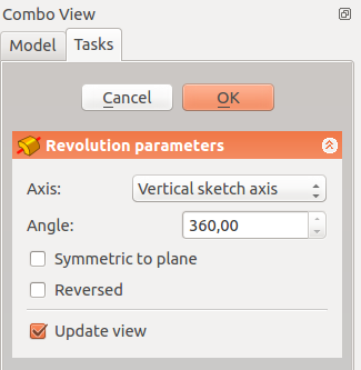
When creating a revolution, the Revolution parameters dialogue offers several parameters specifying how the sketch should be revolved.
 |
AxisThis option specifies the axis about which the sketch is to be revolved.
AngleThis controls the angle through which the revolution is to be formed, e.g. 360° would be a full, contiguous revolution. The images in the examples section demonstrate some of the possibilities with specifying different angles. It is not possible to specify negative angles (use the Reversed option instead) or angles greater than 360°. Symmetric to planeIf checked, the revolution will extend half of the specified angle in both directions from the sketch plane. ReversedIf checked, the direction of revolution is reversed from default clockwise to counterclockwise. |
Свойства
Below are properties which can be defined after creation of the feature. Data properties Base and Axis are uneditable.
- ДанныеAngle: angle of rotation. See Angle.
- ДанныеLabel: label given to the operation, can be changed at convenience.
- ДанныеMidplane: true or false. See Symmetric to plane.
- ДанныеReversed: true or false. See Reversed.
- ДанныеRefine: true or false. If set to true, cleans the solid from residual edges left by features. See Part RefineShape for more details.
Примеры

Useful links
A detailed example of use on the forum.
- Инструменты структуры: Part, Group
- Вспомогательные инструменты: Create body, Create sketch, Edit sketch, Map sketch to face
- Инструменты моделирования
- Инструменты данных: Create a datum point, Create a datum line, Create a datum plane, Create a local coordinate system, Create a shape binder, Create a clone
- Аддитивные инструменты: Pad, Revolution, Additive loft, Additive pipe, Additive box, Additive cone, Additive cylinder, Additive ellipsoid, Additive prism, Additive sphere, Additive torus, Additive wedge
- Субстрактивные инструменты: Pocket, Hole, Groove, Subtractive loft, Subtractive pipe, Subtractive box, Subtractive cone, Subtractive cylinder, Subtractive ellipsoid, Subtractive prism, Subtractive sphere, Subtractive torus, Subtractive wedge
- Инструменты трансформации: Mirrored, Linear Pattern, Polar Pattern, Create MultiTransform
- Отделочные инструменты: Fillet, Chamfer, Draft, Thickness
- Бинарные: Boolean operation
- Дополнительно: Migrate, Shaft design wizard, Involute gear
- Инструменты контекстного меню: Set tip, Move object to other body, Move object after other object
- Начинающим
- Установка: Загрузка, Windows, Linux, Mac, Дополнительных компонентов, Docker, AppImage, Ubuntu Snap
- Базовая: О FreeCAD, Интерфейс, Навигация мыши, Методы выделения, Имя объекта, Настройки, Верстаки, Структура документа, Свойства, Помоги FreeCAD, Пожертвования
- Помощь: Учебники, Видео учебники
- Верстаки: Std Base, Arch, Assembly, CAM, Draft, FEM, Inspection, Mesh, OpenSCAD, Part, PartDesign, Points, Reverse Engineering, Robot, Sketcher, Spreadsheet, Surface, TechDraw, Test Framework
