Part Cylinder/es: Difference between revisions
Emagdalena (talk | contribs) (Languages spanish) |
(Updating to match new version of source page) |
||
| (26 intermediate revisions by 3 users not shown) | |||
| Line 1: | Line 1: | ||
<languages/> |
|||
{{GuiCommand/es|Name=Part_Cylinder|Workbenches=Pieza,Completo}} |
|||
{{Docnav |
|||
Crea un cilindro paramétrico simple, con los parámetros de posición, ángulo, radio y altura. |
|||
|[[Part_Box|Box]] |
|||
|[[Part_Sphere|Sphere]] |
|||
|[[Part_Workbench|Part]] |
|||
|IconL=Part_Box.svg |
|||
|IconR=Part_Sphere.svg |
|||
|IconC=Workbench_Part.svg |
|||
}} |
|||
<div class="mw-translate-fuzzy"> |
|||
Por defecto es un cilindro completo posicionado con el centro de uno de sus caras circulares coincidente con el origen global (punto 0,0,0), con un radio de 2mm y una altura de 10mm. |
|||
{{GuiCommand/es|Name=Part Cylinder|Name/es=Part Cylinder|MenuLocation=Part → Cylinder||Workbenches=[[Part_Workbench/es|Part]], Complete|SeeAlso=[[Part CreatePrimitives/es|Part CreatePrimitives]]}} |
|||
</div> |
|||
==Description== |
|||
Las propiedades se pueden editar después en la pestaña de datos del cilindro: |
|||
The [[Image:Part_Cylinder.svg|24px]] '''Part Cylinder''' command creates a parametric cylinder solid. It is the result of extruding a circular arc along a straight path. In the coordinate system defined by its {{PropertyData|Placement}} property, the bottom face of the cylinder lies on the XY plane with its center at the origin. |
|||
El parámetro de ángulo permite la creación de una porción del cilindro (está establecido como 360° por defecto). |
|||
A Part Cylinder can be turned into a segment of a cylinder by changing its {{PropertyData|Angle}} property. |
|||
La altura es la distancia en el eje Z. |
|||
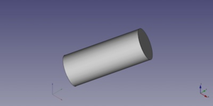
[[Image:Part_Cylinder_Example.png|400px]] |
|||
El radio define un plano en X-Y. |
|||
==Usage== |
|||
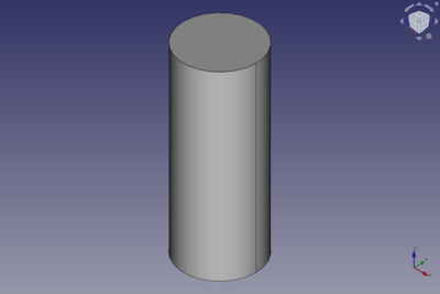
[[File:cylinder.png|650px|a cylinder created with the Cylinder tool]] |
|||
# There are several ways to invoke the command: |
|||
{{languages/es | {{en|Part Cylinder}} {{fr|Part Cylinder/fr}} {{it|Part Cylinder/it}} {{se|Part Cylinder/se}} }} |
|||
#* Press the {{Button|[[Image:Part_Cylinder.svg|16px]] [[Part_Cylinder|Part Cylinder]]}} button. |
|||
#* Select the {{MenuCommand|Part → Primitives → [[Image:Part_Cylinder.svg|16px]] Cylinder}} option from the menu. |
|||
# The cylinder is created. |
|||
# Optionally change the dimensions and {{PropertyData|Placement}} of the cylinder by doing one of the following: |
|||
#* Double-click the object in the [[Tree_view|Tree view]]: |
|||
#*# The {{MenuCommand|Geometric Primitives}} task panel opens. |
|||
#*# Change one or more properties. |
|||
#*# The object is dynamically updated in the [[3D_view|3D view]]. |
|||
#*# Press the {{Button|OK}} button. |
|||
#* Change the properties in the [[Property_editor|Property editor]]. |
|||
#* Change the {{PropertyData|Placement}} with the [[Image:Std_TransformManip.svg|16px]] [[Std_TransformManip|Std TransformManip]] command. |
|||
== Example == |
|||
[[Image:Part_Cylinder_Scripting_Example.png|thumb|Part Cylinder from the scripting example]] |
|||
A Part Cylinder object created with the [[#Scripting|scripting example]] below is shown here. |
|||
== Notes == |
|||
* A Part Cylinder can also be created with the [[Image:Part_Primitives.svg|16px]] [[Part_Primitives|Part Primitives]] command. With that command you can specify the dimensions and placement at creation time. |
|||
== Properties == |
|||
See also: [[Property_editor|Property editor]]. |
|||
A Part Cylinder object is derived from a [[Part_Feature|Part Feature]] object and inherits all its properties. It also has the following additional properties: |
|||
=== Data === |
|||
{{TitleProperty|Attachment}} |
|||
The object has the same attachment properties as a [[Part_Part2DObject#Data|Part Part2DObject]]. |
|||
{{TitleProperty|Cylinder}} |
|||
* {{PropertyData|Radius|Length}}: The radius of the circular arc that defines the cylinder. The default is {{Value|2mm}}. |
|||
* {{PropertyData|Height|Length}}: The height of the cylinder. The default is {{Value|10mm}}. |
|||
* {{PropertyData|Angle|Angle}}: The angle of the circular arc that defines the cylinder. Valid range: {{Value|0° < value <= 360°}}. The default is {{Value|360°}}. If it is smaller than {{Value|360°}} the resulting solid will be a segment of a cylinder. |
|||
{{TitleProperty|Prism}} |
|||
* {{PropertyData|First Angle|Angle}}: The angle between the extrusion direction of the cylinder and its positive Z axis, measured around its Y axis. The angle is positive towards its positive X axis. Valid range: {{Value|0° <= value < 90°}}. The default is {{Value|0°}}. {{Version|0.20}} |
|||
* {{PropertyData|Second Angle|Angle}}: The angle between the extrusion direction of the cylinder and its positive Z axis, measured around its X axis. The angle is positive towards its positive Y axis. Valid range: {{Value|0° <= value < 90°}}. The default is {{Value|0°}}. {{Version|0.20}} |
|||
== Scripting == |
|||
See also: [https://freecad.github.io/SourceDoc/ Autogenerated API documentation], [[Part_scripting|Part scripting]] and [[FreeCAD_Scripting_Basics|FreeCAD Scripting Basics]]. |
|||
A Part Cylinder can be created with the {{Incode|addObject()}} method of the document: |
|||
{{Code|code= |
|||
cylinder = FreeCAD.ActiveDocument.addObject("Part::Cylinder", "myCylinder") |
|||
}} |
|||
* Where {{Incode|"myCylinder"}} is the name for the object. |
|||
* The function returns the newly created object. |
|||
Example: |
|||
{{Code|code= |
|||
import FreeCAD as App |
|||
doc = App.activeDocument() |
|||
cylinder = doc.addObject("Part::Cylinder", "myCylinder") |
|||
cylinder.Radius = 10 |
|||
cylinder.Height = 50 |
|||
cylinder.Placement = App.Placement(App.Vector(5, 10, 15), App.Rotation(75, 60, 30)) |
|||
doc.recompute() |
|||
}} |
|||
{{Docnav |
|||
|[[Part_Box|Box]] |
|||
|[[Part_Sphere|Sphere]] |
|||
|[[Part_Workbench|Part]] |
|||
|IconL=Part_Box.svg |
|||
|IconR=Part_Sphere.svg |
|||
|IconC=Workbench_Part.svg |
|||
}} |
|||
{{Part_Tools_navi{{#translation:}}}} |
|||
{{Userdocnavi{{#translation:}}}} |
|||
Latest revision as of 08:55, 4 March 2022
|
|
| Ubicación en el Menú |
|---|
| Part → Cylinder |
| Entornos de trabajo |
| Part, Complete |
| Atajo de teclado por defecto |
| Ninguno |
| Introducido en versión |
| - |
| Ver también |
| Part CreatePrimitives |
Description
The Part Cylinder command creates a parametric cylinder solid. It is the result of extruding a circular arc along a straight path. In the coordinate system defined by its DatosPlacement property, the bottom face of the cylinder lies on the XY plane with its center at the origin.
A Part Cylinder can be turned into a segment of a cylinder by changing its DatosAngle property.
Usage
- There are several ways to invoke the command:
- Press the
Part Cylinder button.
- Select the Part → Primitives →
Cylinder option from the menu.
- Press the
- The cylinder is created.
- Optionally change the dimensions and DatosPlacement of the cylinder by doing one of the following:
- Double-click the object in the Tree view:
- The Geometric Primitives task panel opens.
- Change one or more properties.
- The object is dynamically updated in the 3D view.
- Press the OK button.
- Change the properties in the Property editor.
- Change the DatosPlacement with the
Std TransformManip command.
- Double-click the object in the Tree view:
Example

A Part Cylinder object created with the scripting example below is shown here.
Notes
- A Part Cylinder can also be created with the
Part Primitives command. With that command you can specify the dimensions and placement at creation time.
Properties
See also: Property editor.
A Part Cylinder object is derived from a Part Feature object and inherits all its properties. It also has the following additional properties:
Data
Attachment
The object has the same attachment properties as a Part Part2DObject.
Cylinder
- DatosRadius (
Length): The radius of the circular arc that defines the cylinder. The default is2mm. - DatosHeight (
Length): The height of the cylinder. The default is10mm. - DatosAngle (
Angle): The angle of the circular arc that defines the cylinder. Valid range:0° < value <= 360°. The default is360°. If it is smaller than360°the resulting solid will be a segment of a cylinder.
Prism
- DatosFirst Angle (
Angle): The angle between the extrusion direction of the cylinder and its positive Z axis, measured around its Y axis. The angle is positive towards its positive X axis. Valid range:0° <= value < 90°. The default is0°. introduced in version 0.20 - DatosSecond Angle (
Angle): The angle between the extrusion direction of the cylinder and its positive Z axis, measured around its X axis. The angle is positive towards its positive Y axis. Valid range:0° <= value < 90°. The default is0°. introduced in version 0.20
Scripting
See also: Autogenerated API documentation, Part scripting and FreeCAD Scripting Basics.
A Part Cylinder can be created with the addObject() method of the document:
cylinder = FreeCAD.ActiveDocument.addObject("Part::Cylinder", "myCylinder")
- Where
"myCylinder"is the name for the object. - The function returns the newly created object.
Example:
import FreeCAD as App

doc = App.activeDocument()

cylinder = doc.addObject("Part::Cylinder", "myCylinder")
cylinder.Radius = 10
cylinder.Height = 50
cylinder.Placement = App.Placement(App.Vector(5, 10, 15), App.Rotation(75, 60, 30))

doc.recompute()
- Primitives: Box, Cylinder, Sphere, Cone, Torus, Tube, Create primitives, Shape builder
- Creation and modification: Extrude, Revolve, Mirror, Fillet, Chamfer, Make face from wires, Ruled Surface, Loft, Sweep, Section, Cross sections, 3D Offset, 2D Offset, Thickness, Projection on surface, Attachment
- Boolean: Make compound, Explode Compound, Compound Filter, Boolean, Cut, Fuse, Common, Connect, Embed, Cutout, Boolean fragments, Slice apart, Slice, XOR
- Measure: Measure Linear, Measure Angular, Measure Refresh, Clear All, Toggle All, Toggle 3D, Toggle Delta
- Getting started
- Installation: Download, Windows, Linux, Mac, Additional components, Docker, AppImage, Ubuntu Snap
- Basics: About FreeCAD, Interface, Mouse navigation, Selection methods, Object name, Preferences, Workbenches, Document structure, Properties, Help FreeCAD, Donate
- Help: Tutorials, Video tutorials
- Workbenches: Std Base, Assembly, BIM, CAM, Draft, FEM, Inspection, Mesh, OpenSCAD, Part, PartDesign, Points, Reverse Engineering, Robot, Sketcher, Spreadsheet, Surface, TechDraw, Test Framework
- Hubs: User hub, Power users hub, Developer hub
