Draft Edit/sv: Difference between revisions
(Updating to match new version of source page) |
(Updating to match new version of source page) |
||
| Line 1: | Line 1: | ||
{{Page_in_progress}} |
|||
<languages/> |
<languages/> |
||
{{Docnav |
{{Docnav |
||
|[[Draft_PointLinkArray|PointLinkArray]] |
|||
|[[Draft_Scale|Scale]] |
|||
|[[Draft_SubelementHighlight| |
|[[Draft_SubelementHighlight|SubelementHighlight]] |
||
|[[Draft_Module|Draft]] |
|[[Draft_Module|Draft]] |
||
|IconL= |
|IconL=Draft_PointLinkArray.svg |
||
|IconR=Draft_SubelementHighlight.svg |
|IconR=Draft_SubelementHighlight.svg |
||
|IconC=Workbench_Draft.svg |
|IconC=Workbench_Draft.svg |
||
| Line 18: | Line 20: | ||
Detta verktyg tillåter dig att grafiskt redigera vissa egenskaper av det markerade objektet, som hörnen i en tråd, eller längden och bredden på en Rektangel, eller radien på en Cirkel. |
Detta verktyg tillåter dig att grafiskt redigera vissa egenskaper av det markerade objektet, som hörnen i en tråd, eller längden och bredden på en Rektangel, eller radien på en Cirkel. |
||
</div> |
</div> |
||
It does nothing more than enter the object's edit mode. Another way to edit the object is by double clicking on the element in the tree view. |
It does nothing more than enter the object's edit mode. Another way to edit the object is by double clicking on the element in the tree view. |
||
[[Image: |
[[Image:Draft_edit_ex_01.jpg|400px]] |
||
{{Caption| |
{{Caption|Example presentation of a wire, an arc and a cubic bezier curve.}} |
||
[[Image:Draft_edit_ex_02.jpg|400px]] |
|||
{{Caption|Here wire selected}} |
|||
[[Image:Draft_edit_ex_03.jpg|400px]] |
|||
{{Caption|Here selected wire marked for editing}} |
|||
==Bruk== |
==Bruk== |
||
# Select the object you want to change in the [[tree_view|tree view]]. The selected object becomes {{ColoredText|rgb(102, 255, 102)|rgb(8, 8, 8)| green}} in drawing window. {{Version|0.19}} |
|||
# Select an object. |
|||
# Press the {{Button|[[Image:Draft_Edit.svg|16px]] [[ |
# Press the {{Button|[[Image:Draft_Edit.svg|16px]] [[Draft_Edit|Draft Edit]]}} button, or double-click the object in the [[Tree_view|tree view]], or Select the {{MenuCommand|Edit → [[Image:Std_Edit.svg|16px]] Toggle Edit mode}} option from the menu. The selected object becomes {{ColoredText|rgb(8, 8, 8)|rgb(255, 255, 255)| black}} with {{Value|white}} vertices and in the [[combo_view|Combo View]] panel an edit window is opened. |
||
# Click on a point that you wish to move. |
|||
# Click another point on the 3D view, or type a [[Draft_Coordinates|coordinate]] and press the {{Button|[[Image:Draft_AddPoint.svg|16px]] [[Draft_AddPoint|add point]]}} button. |
|||
| ⚫ | |||
[[Image:Draft_edit_Combo_View_start.jpg|300px]] |
|||
| ⚫ | Version 0.19 added new functionalities to Draft Edit such as multiple object editing and custom context menu. To display the context menu, user can press {{KEY|E}} key or {{KEY|Alt}}+{{KEY|Left click}} while overing an edit node or an edited object. Beware not every object contains custom options, so the context menu will be only displayed for supported objects. |
||
{{Caption|Draft Edit Combo View start}} |
|||
[[Image:Draft_edit_Combo_View_editmode.jpg|300px]] |
|||
| ⚫ | The tool mostly works on Draft objects: [[ |
||
{{Caption|Draft Edit Combo View change after selecting specific vertex}} |
|||
# Then press {{Button|Ctrl}} + {{Button|alt}} or {{Button|Shift}} + {{Button|alt}} buttons (for Linux OS) respectively {{Button|alt}} button (for Windows OS) and move mouse cursor |
|||
##* '''over a line''', then {{Button|Left click}} and the appearing white field shows {{Value|add point}}. If you click on that field a new vertex is added to the line. If you release buttons and push {{Button|esc}} the command will be canceled. |
|||
[[Image:Draft_edit_add_point.jpg|500px]] |
|||
{{Caption|Draft Edit 3D View add point}} |
|||
##* '''over a vertex''', then {{Button|Left click}} and the appearing white field shows {{Value|delete point}}. If you click on that field the vertex is removed from the line. If you release buttons and push {{Button|esc}} the command will be canceled. |
|||
[[Image:Draft_edit_delete_point.jpg|500px]] |
|||
{{Caption|Draft Edit 3D View delete point}} |
|||
| ⚫ | |||
| ⚫ | <strike>Version 0.19 added new functionalities to Draft Edit such as multiple object editing and custom context menu. To display the context menu, user can press {{KEY|E}} key or {{KEY|Alt}}+{{KEY|Left click}} while overing an edit node or an edited object. Beware not every object contains custom options, so the context menu will be only displayed for supported objects. |
||
</strike> |
|||
| ⚫ | The tool {{ColoredText||DarkRed|mostly ??}} works on Draft objects: [[Image:Draft_Wire.svg|24px]][[Draft_Wire|Draft Wires]], [[Image:Draft_Line.svg|24px]][[Draft_Line|Draft Lines]], [[Image:Draft_Rectangle.svg|24px]][[Draft_Rectangle|Draft Rectangles]], [[Image:Draft_Circle.svg|24px]][[Draft_Circle|Draft Circles]], [[Image:Draft_Arc.svg|24px]][[Draft_Arc|Draft Arcs]], [[Image:Draft_Polygon.svg|24px]][[Draft_Polygon|Draft Polygons]], and [[Image:Draft_BSpline.svg|24px]][[Draft_BSpline|Draft BSplines]]. Other object types must first be converted to these objects. |
||
==Options== |
==Options== |
||
| Line 54: | Line 77: | ||
==Scripting== |
==Scripting== |
||
{{Emphasis|See also:}} [[Draft_API|Draft API]] and [[FreeCAD_Scripting_Basics|FreeCAD Scripting Basics]]. |
|||
See also: [https://www.freecadweb.org/api Autogenerated API documentation] and [[FreeCAD Scripting Basics|FreeCAD Scripting Basics]]. |
|||
There is no programming interface available for the Edit tool. Each object is modified by changing its attributes directly. |
There is no programming interface available for the Edit tool. Each object is modified by changing its attributes directly. |
||
{{Docnav |
{{Docnav |
||
|[[Draft_PointLinkArray|PointLinkArray]] |
|||
|[[Draft_Scale|Scale]] |
|||
|[[Draft_SubelementHighlight| |
|[[Draft_SubelementHighlight|SubelementHighlight]] |
||
|[[Draft_Module|Draft]] |
|[[Draft_Module|Draft]] |
||
|IconL= |
|IconL=Draft_PointLinkArray.svg |
||
|IconR=Draft_SubelementHighlight.svg |
|IconR=Draft_SubelementHighlight.svg |
||
|IconC=Workbench_Draft.svg |
|IconC=Workbench_Draft.svg |
||
| Line 69: | Line 94: | ||
{{Draft Tools navi{{#translation:}}}} |
{{Draft Tools navi{{#translation:}}}} |
||
{{Userdocnavi{{#translation:}}}} |
{{Userdocnavi{{#translation:}}}} |
||
{{clear}} |
|||
Revision as of 09:47, 20 May 2021
|
|
| Menyplacering |
|---|
| Draft → Edit |
| Arbetsbänkar |
| Skiss |
| Standard genväg |
| Ingen |
| Introducerad i version |
| - |
| Se även |
| Ingen |
Beskrivning
Detta verktyg tillåter dig att grafiskt redigera vissa egenskaper av det markerade objektet, som hörnen i en tråd, eller längden och bredden på en Rektangel, eller radien på en Cirkel.
It does nothing more than enter the object's edit mode. Another way to edit the object is by double clicking on the element in the tree view.
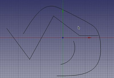
Example presentation of a wire, an arc and a cubic bezier curve.
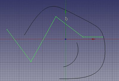
Here wire selected
Here selected wire marked for editing
Bruk
- Select the object you want to change in the tree view. The selected object becomes green in drawing window. introduced in version 0.19
- Press the
Draft Edit button, or double-click the object in the tree view, or Select the Edit →
Toggle Edit mode option from the menu. The selected object becomes black with
whitevertices and in the Combo View panel an edit window is opened.
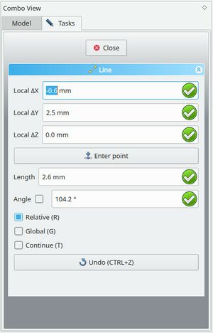
Draft Edit Combo View start
Draft Edit Combo View change after selecting specific vertex
- Then press Ctrl + alt or Shift + alt buttons (for Linux OS) respectively alt button (for Windows OS) and move mouse cursor
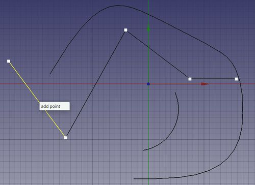
- over a line, then Left click and the appearing white field shows
add point. If you click on that field a new vertex is added to the line. If you release buttons and push esc the command will be canceled.
- over a line, then Left click and the appearing white field shows
Draft Edit 3D View add point
- over a vertex, then Left click and the appearing white field shows
delete point. If you click on that field the vertex is removed from the line. If you release buttons and push esc the command will be canceled.
- over a vertex, then Left click and the appearing white field shows
Draft Edit 3D View delete point
- Press Esc or the Close (O) button in the task panel to complete the current command.
Version 0.19 added new functionalities to Draft Edit such as multiple object editing and custom context menu. To display the context menu, user can press E key or Alt+Left click while overing an edit node or an edited object. Beware not every object contains custom options, so the context menu will be only displayed for supported objects.
The tool mostly ?? works on Draft objects: Draft Wires,
Draft Lines,
Draft Rectangles,
Draft Circles,
Draft Arcs,
Draft Polygons, and
Draft BSplines. Other object types must first be converted to these objects.
Options
- Redigeringsverktyget fungerar endast på ett markerat objekt åt gången.
- Redigeringsläget fungerar endast på Skiss Trådar, Rektanglar, Cirklar och Cirkelbågar. Andra objekttyper måste först konverteras till Skissobjekt.
- Klicka på ett redigeringshörn för att flytta det, klicka igen för att släppa det.
- Nedtryckning av CTRL kommer att snäppa din punkt till tillgängliga snäpp-punkter.
- Nedtryckning av SKIFT kommer att koppla ihop x och y värdena , så att formen behålls
- Om du trycker på ESC så avbryts funktionen.
- Om du klickar på redigeringskanppen igen så avslutas redigeringsläget
- Skriv in siffror för att manuellt mata in en koordinat.
Some objects allow you to insert or delete points:
- Press the
add point button, and then click on the wire or spline to add a new point.
- Press the
remove point button, and then click on a point along the wire or spline to remove it.
Scripting
See also: Autogenerated API documentation and FreeCAD Scripting Basics.
There is no programming interface available for the Edit tool. Each object is modified by changing its attributes directly.
- Drafting: Line, Polyline, Fillet, Arc, Arc by 3 points, Circle, Ellipse, Rectangle, Polygon, B-spline, Cubic Bézier curve, Bézier curve, Point, Facebinder, ShapeString, Hatch
- Annotation: Text, Dimension, Label, Annotation styles, Annotation scale
- Modification: Move, Rotate, Scale, Mirror, Offset, Trimex, Stretch, Clone, Array, Polar array, Circular array, Path array, Path link array, Point array, Point link array, Edit, Subelement highlight, Join, Split, Upgrade, Downgrade, Wire to B-spline, Draft to sketch, Set slope, Flip dimension, Shape 2D view
- Draft Tray: Select plane, Set style, Toggle construction mode, AutoGroup
- Snapping: Snap lock, Snap endpoint, Snap midpoint, Snap center, Snap angle, Snap intersection, Snap perpendicular, Snap extension, Snap parallel, Snap special, Snap near, Snap ortho, Snap grid, Snap working plane, Snap dimensions, Toggle grid
- Miscellaneous: Apply current style, Layer, Manage layers, Add a new named group, Move to group, Select group, Add to construction group, Toggle normal/wireframe display, Create working plane proxy, Heal, Show snap toolbar
- Additional: Constraining, Pattern, Preferences, Import Export Preferences, DXF/DWG, SVG, OCA, DAT
- Context menu:
- Layer container: Merge layer duplicates, Add new layer
- Layer: Activate this layer, Select layer contents
- Text: Open hyperlinks
- Wire: Flatten
- Working plane proxy: Write camera position, Write objects state
- Getting started
- Installation: Download, Windows, Linux, Mac, Additional components, Docker, AppImage, Ubuntu Snap
- Basics: About FreeCAD, Interface, Mouse navigation, Selection methods, Object name, Preferences, Workbenches, Document structure, Properties, Help FreeCAD, Donate
- Help: Tutorials, Video tutorials
- Workbenches: Std Base, Arch, Assembly, CAM, Draft, FEM, Inspection, Mesh, OpenSCAD, Part, PartDesign, Points, Reverse Engineering, Robot, Sketcher, Spreadsheet, Start, Surface, TechDraw, Test Framework, Web
- Hubs: User hub, Power users hub, Developer hub


