Problème de dénomination topologique
Introduction
Le problème de dénomination topologique dans FreeCAD fait référence au conséquences d’une forme qui change de nom interne après une opération de modélisation (protusion, coupe, union, chanfrein, congé, etc.). Cela a pour conséquence la casse ou le calcul incorrect d'autres caractéristiques paramétriques dépendantes de cette forme. Ce problème concerne tous les objets dans FreeCAD, mais est particulièrement important lors de la création de solides avec l'atelier PartDesign et lors de la cotation de ces solides avec l'atelier TechDraw.
- Dans PartDesign, si une entité est prise en charge sur une face (ou une arête ou un sommet), elle peut se rompre si le solide sous-jacent change de taille ou d'orientation, car la face d'origine (ou l'arête ou le sommet) peut être renommé de manière interne.
- Dans TechDraw, si une dimension mesure la longueur d'un bord projeté, elle risque de se briser si le modèle 3D est modifié, car les sommets peuvent être renommés, modifiant ainsi le bord mesuré.
Le problème de la dénomination topologique est un problème complexe en modélisation CAO qui découle de la façon dont les routines internes FreeCAD traitent les mises à jour des formes géométriques créées avec le noyau OCCT. Depuis FreeCAD 0.18, des efforts sont en cours pour améliorer la gestion des formes afin de réduire ou d’éliminer ces problèmes.
Le problème de dénomination topologique affecte et trouble le plus souvent les nouveaux utilisateurs de FreeCAD. Dans PartDesign, il est conseillé à l'utilisateur de suivre les meilleures pratiques décrites dans la page Édition de fonctions. L'utilisation d'objets de référence pris en charge, tels que les plans et les systèmes de coordonnées locaux, est fortement recommandée pour produire des modèles qui ne sont pas facilement sujets à de telles erreurs topologiques. Dans TechDraw, il est conseillé à l'utilisateur d'ajouter des cotes uniquement lorsque le modèle 3D est terminé et ne sera plus modifié.
Exemple
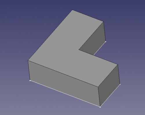
1. Dans l'atelier PartDesign, créez un corps PartDesign, puis utilisez nouvelle esquisse PartDesign et sélectionnez le plan XY pour dessiner l'esquisse de base ; effectuez ensuite une protusion PartDesign pour créer un premier solide.
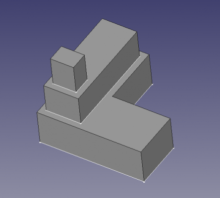
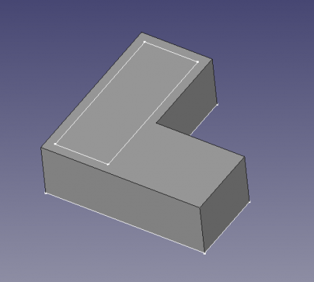
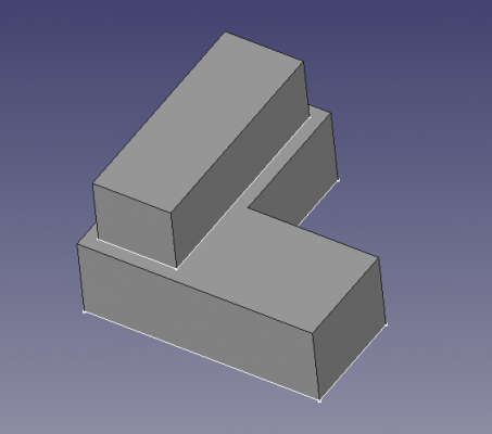
2. Select the top face of the previous solid, and then use PartDesign NewSketch to draw another sketch; then perform a second pad.
 |
|
3. Select the top face of the previous extrusion, and once again create a sketch, and a pad.
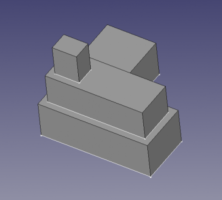
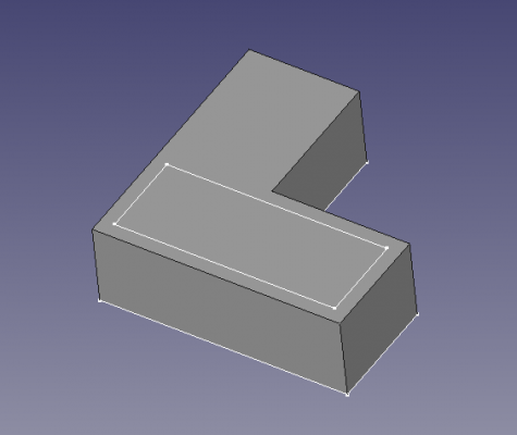
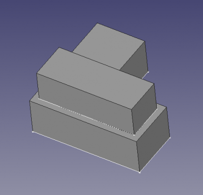
4. Now, double click the second sketch, and modify it so that its length is along the X direction; doing this will recreate the second pad. The third sketch and pad will stay in the same place.
 |
|
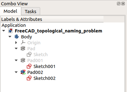
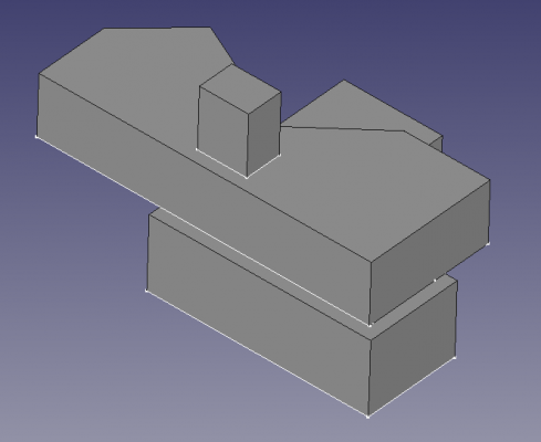
5. Now, double click the second sketch again, and adjust its points so that a portion of it is outside the limits defined by the first pad. By doing this, the second pad will recompute correctly, however, when looking at the tree view, an error will be indicated in the third pad.
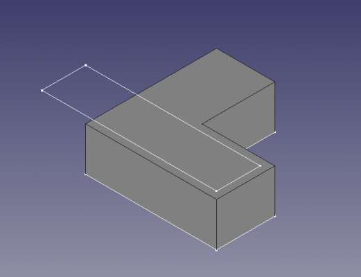 |
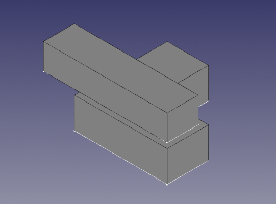
|
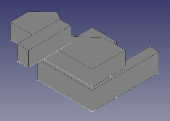
6. By making visible the third sketch and pad, it is clear that the computation of the new solid did not proceed correctly. The third sketch, instead of being supported by the top face of the second pad, appears in a strange place, with its normal oriented towards the X direction. This results in an invalid pad, as this pad would be disconnected from the rest of the PartDesign Body, which is not allowed.
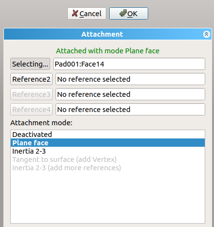
The problem appears to be that when the second sketch was modified, the top face of the second pad was renamed from Face13 to Face14. The third sketch is attached to Face13 as it originally was, but since this face is now on the side (not at the top), the sketch follows its orientation and now is incorrectly positioned.
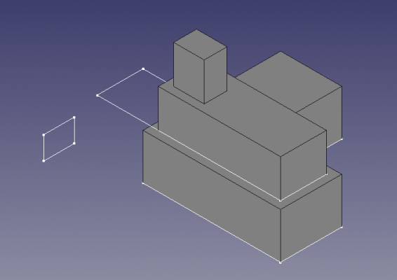 |
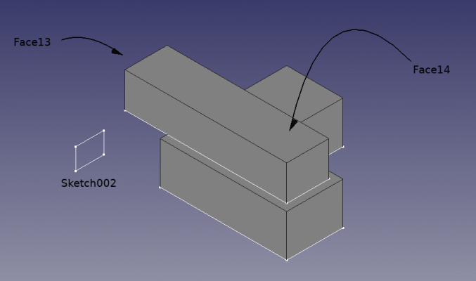
|
7. To fix the issue, the third sketch should be mapped to the top face again. Select the sketch, click on the ellipsis (three dots) next to the DonnéesMap Mode property, and choose the top face of the second pad again. Then the sketch moves to the top of the existing solid, and the third pad is generated without issues.
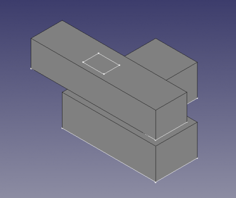 |
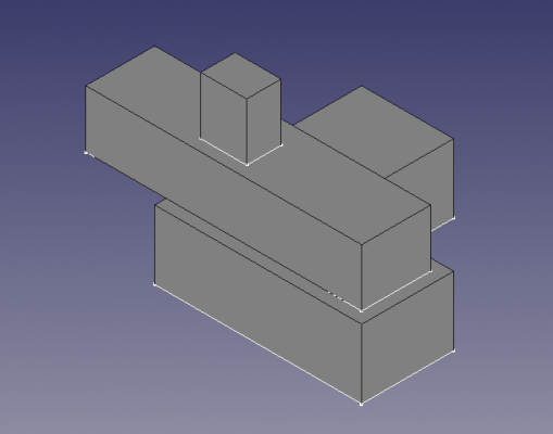
|
Remapping a sketch in this way can be done every time there is a topological naming error, however, this may be tedious if the model is complicated and there are many such sketches that need to be adjusted.
Solution
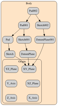
The dependency graph is a tool that is helpful to observe the relationships between the different bodies in the document. Using the original modelling workflow reveals the direct relationship that exists between the sketches and the pads. Like a chain, it is easy to see that this direct dependence will be subject to topological naming problems if any of the links in the sequence changes.
As explained in the feature editing page, a solution to this problem is to support sketches not on faces but on datum planes which are offset from the main planes of the PartDesign Body's Origin.
1. Select the origin of the PartDesign Body and make sure that it is visible. Then select the XY plane, and click on PartDesign Plane. In the attachment offset dialog, give it an offset in the Z direction so that the datum plane is coplanar with the top face of the first pad.
2. Repeat the process but this time add a larger offset so that the second datum plane is coplanar with the top face of the second pad.
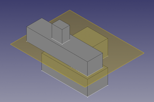 |
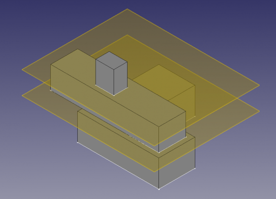
|
3. Select the second sketch, click on the ellipsis next to the DonnéesMap Mode property, and then select the first datum plane. The datum plane is already offset from the body's XY plane, so no further Z offset is required for the sketch.
4. Repeat the process with the third sketch, and select the second datum plane as support. Again, no further Z offset is necessary.
5. The dependency graph now shows that the sketches and pads are supported by the datum planes. This model is more stable as each sketch can be modified essentially independently from each other.
6. Double click the second sketch and modify the shape. The second pad should update immediately without causing topological problems with the third sketch and the third pad.
7. In fact, every sketch can be modified without interfering with each other's pads. As long as the pads have sufficient extrusion length, so that they touch and form a contiguous solid, the entire body will be valid.
Final remarks
Adding datum objects is more work for the user but ultimately produces more stable models that are less subject to the topological naming problem.
Naturally, datum objects can be created before any sketches are drawn, and pads are produced. This may be helpful to visualize the approximate shape and dimensions of the final body.
Datum planes can also be based on other datum planes. This creates a chain of dependencies that could also result in topological problems; however, since datum planes are very simple objects, the risks of having these issues is less than if the face of a solid object is used as support.
Datum objects, points, lines, planes, and coordinate systems, may also be useful as reference geometry, that is, as visual aids to show the important features in the model, even if no sketch is directly attached to them.
- Pages : Page par défaut, Page à partir d'un modèle, Redessiner une page, Tout imprimer
- Vues : Vue, Vue active, Groupe de projections, Vue en coupe, Vue en coupe complexe, Vue détaillée, Vue d'un objet Draft, Vue d'un objet Arch, Vue d'un objet Spreadsheet, Fenêtre de rognage, Copier une vue, Projection de forme
- Empilement : Empiler en haut, Empiler en bas, Empiler vers le haut, Empiler vers le bas
- Décorations : Hachures par motif, Hachures géométriques, Symbole, Image, Bascule des cadres
- Cotes : Cote de longueur, Cote horizontale, Cote verticale, Cote de rayon, Cote de diamètre, Cote angulaire, Cote angulaire par 3 points, Cote étendue horizontale, Cote étendue verticale, Lier une cote, Infobulle, Cote axonométrique, Cote à partir des points du repère, Réparation des cotes
- Annotations : Annotation, Ligne de référence, Annotation texte enrichi, Point cosmétique, Points médians, Sommets quadrants, Ligne centrale à une face, Ligne centrale entre 2 lignes, Ligne centrale entre 2 points, Ligne cosmétique par 2 points, Cercle cosmétique, Apparence des lignes, Montrer tout, Soudure, Symbole d'état de surface, Tolérance de trou/d'arbre
- Extensions :
- Attributs et modifications : Sélection des attributs, Modification des attributs, Prolonger, Raccourcir, Verrouiller/déverrouiller, Position d'une vue en coupe, Aligner horizontalement, Aligner verticalement, Aligner obliquemement, Cascade horizontale, Cascade verticale, Cascade oblique, Calculer l'aire des faces sélectionnées, Calculer la longueur d'arc d'arêtes sélectionnées, Personnaliser le format d'infobulle
- Lignes centrales, filetage et taraudage : Axes de centrage, Axes de centrage de trous/vis, Corps de taraudage, Taraudage, Corps de filetage, Filetage, Intersection de lignes, Ajouter un sommet décalé, Cercle, Arc, Cercle par 3 points, Ligne parallèle, Ligne perpendiculaire
- Cotes : Cotes horizontales, Cotes verticales, Cotes obliques, Cotes parallèles horizontales, Cotes parallèles verticales, Cotes parallèles obliques, Cote horizontale chanfrein, Cote verticale chanfrein, Longueur d'arc, Diamètre '⌀', Section tube '〼', Supprimer les symboles, Plus de décimales, Moins de décimales
- Exportation : Exporter au format SVG, Exporter au format DXF
- Fonctions supplémentaires : Groupe de lignes, Modèles, Hachures, Dimensionnement géométrique et tolérance, Préférences
- Outils structure : Part, Groupe
- Outils d'aide : Créer un corps, Créer une esquisse, Éditer une esquisse, Plaquer une esquisse sur une face
- Outils de modélisation
- Outils de référence : Créer un point de référence, Créer une ligne de référence, Créer un plan de référence, Créer un système de coordonnées local, Créer une forme liée, Créer une forme liée du sous-objet(s), Créer un clone
- Outils additifs : Protrusion, Révolution, Lissage additif, Balayage additif, Hélice additive, Cube additif, Cylindre additif, Sphère additive, Cône additif, Ellipsoïde additif, Tore additif, Prisme additif, Pyramide tronquée additive
- Outils soustractifs : Cavité, Perçage, Rainure, Lissage soustractif, Balayage soustractif, Hélice soustractive, Cube soustractif, Cylindre soustractif, Sphère soustractive, Cône soustractif, Ellipsoïde soustractif, Tore soustractif, Prisme soustractif, Pyramide tronquée soustractive
- Outils de transformation : Symétrie, Répétition linéaire, Répétition circulaire, Transformation multiple, Mise à l'échelle
- Fonctions d'habillage : Congé, Chanfrein, Dépouille, Évidement
- Opérations Booléenne : Opérations Booléenne
- Primitives : Box, Cylindre, Sphère, Cône, Tore, Tube, Primitives, Générateur de formes
- Création et modification des objets : Extrusion, Révolution, Miroir, Congé, Chanfrein, Créer une face, Surface réglée, Lissage, Balayage, Section, Coupes, Décalage 3D, Décalage 2D, Évidement, Projection sur surface, Ancrage
---
- Booléen : Créé un composé, Éclater le composé, Filtre composé, Opération booléenne, Soustraction, Union, Intersection, Connecter, Intégrer, Découper, Fragments booléens, Séparer/exploser, Scinder, OU exclusif
- Mesure : Mesure linéaire, Mesure Angulaire, Rafraîchir les mesures, Effacer toute mesure, Tout basculer, Mesures dans la 3D, Mesures selon le repère global
- Autre outils : Importation, Exportation, Sélection par zone, Forme à partir d'un maillage, Points à partir d'un maillage, Convertir en solide, Inverser les formes, Copie simple, Copie transformée, Copie d'un élément, Affiner la forme, Vérifier la géométrie, Supprimer la fonctionnalité, Apparence, Définir les couleurs
- Démarrer avec FreeCAD
- Installation : Téléchargements, Windows, Linux, Mac, Logiciels supplémentaires, Docker, AppImage, Ubuntu Snap
- Bases : À propos de FreeCAD, Interface, Navigation par la souris, Méthodes de sélection, Objet name, Préférences, Ateliers, Structure du document, Propriétés, Contribuer à FreeCAD, Faire un don
- Aide : Tutoriels, Tutoriels vidéo
- Ateliers : Std Base, Arch, Assembly, CAM, Draft, FEM, Inspection, Mesh, OpenSCAD, Part, PartDesign, Points, Reverse Engineering, Robot, Sketcher, Spreadsheet, Surface, TechDraw, Test
