Draft Edit/es: Difference between revisions
No edit summary |
No edit summary |
||
| Line 42: | Line 42: | ||
==Utilización== |
==Utilización== |
||
# Seleccione el objeto que desea cambiar en la [[Tree_view/es|vista de árbol]]. El objeto seleccionado se convierte en {{ColoredText|rgb(102, 255, 102)|rgb(8, 8, 8)| verde}} en la ventana de dibujo. {{Version/es|0.19}} |
|||
<div class="mw-translate-fuzzy"> |
|||
# Pulse el {{Button|[[Image:Draft_Edit.svg|16px]] [[Draft_Edit/es|Borrador Edición]]}}, o haga doble clic en el objeto en la [[Tree_view/es|vista de árbol]], o seleccione la opción {{MenuCommand|Editar → [[Image:Std_Edit.svg|16px]] Alternar modo de edición}} en el menú. El objeto seleccionado se convierte en {{ColoredText|rgb(8, 8, 8)|rgb(255, 255, 255)|negro}} con vértices {{Value|blanco}} y en el panel [[combo_view/es|Vista de combo]] se abre una ventana de edición. |
|||
# Selecciona un [[Draft Wire/es|contorno]], [[Draft Line/es|línea]], [[Draft Rectangle/es|rectángulo]], [[Draft BSpline/es|BSpline]] o [[Draft Circle/es|circunferencia]] |
|||
# Presiona el botón {{KEY|[[Image:Draft Edit.png|16px]] [[Draft Edit/es|Editar]]}}, o haz doble clic sobre el objeto en el panel del árbol de trabajo |
|||
# Pulsa sobre el punto que quieras mover |
|||
# Indica otro punto en la vista 3D, o escribe unas [[Draft_Coordinates/es|coordenadas]] |
|||
</div> |
|||
[[Image:Draft_edit_Combo_View_start.jpg|300px]] |
[[Image:Draft_edit_Combo_View_start.jpg|300px]] |
||
Revision as of 15:37, 13 June 2021
|
|
| Ubicación en el Menú |
|---|
| Modificación → Editar |
| Entornos de trabajo |
| Borrador, Arquirectura |
| Atajo de teclado por defecto |
| D E |
| Introducido en versión |
| - |
| Ver también |
| Edición estándar, Borrador AdiciónPunto, Borrador EliminaciónPunto |
Descripción
La herramienta Borrador Edición le permite editar gráficamente ciertas propiedades del objeto seleccionado, como:
- los vértices de un
Borrador Hilo
- la longitud y la anchura de un
Borrador Rectángulo
- el radio de un
Borrador Círculo
It does nothing more than enter the object's edit mode. Another way to edit the object is by double clicking on the element in the tree view.
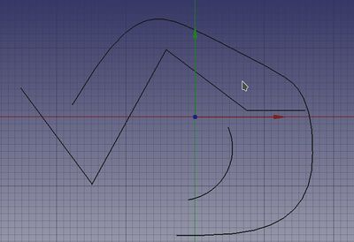
Example presentation of a wire, an arc and a cubic bezier curve.
Here wire selected
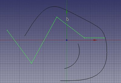
Here selected wire marked for editing
Utilización
- Seleccione el objeto que desea cambiar en la vista de árbol. El objeto seleccionado se convierte en verde en la ventana de dibujo. introducido en la versión 0.19
- Pulse el
Borrador Edición, o haga doble clic en el objeto en la vista de árbol, o seleccione la opción Editar →
Alternar modo de edición en el menú. El objeto seleccionado se convierte en negro con vértices
blancoy en el panel Vista de combo se abre una ventana de edición.
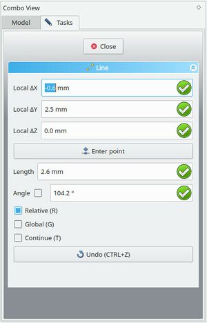
Draft Edit Combo View start
Draft Edit Combo View change after selecting specific vertex
- Then press Ctrl + alt or Shift + alt buttons (for Linux OS) respectively alt button (for Windows OS) and move mouse cursor
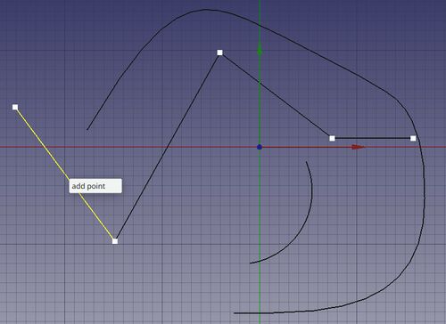
- over a line, then Left click and the appearing white field shows
add point. If you click on that field a new vertex is added to the line. If you release buttons and push esc the command will be canceled.
- over a line, then Left click and the appearing white field shows
Draft Edit 3D View add point
- over a vertex, then Left click and the appearing white field shows
delete point. If you click on that field the vertex is removed from the line. If you release buttons and push esc the command will be canceled.
- over a vertex, then Left click and the appearing white field shows
Draft Edit 3D View delete point
- Press Esc or the Close (O) button in the task panel to complete the current command.
Version 0.19 added new functionalities to Draft Edit such as multiple object editing and custom context menu. To display the context menu, user can press E key or Alt+Left click while overing an edit node or an edited object. Beware not every object contains custom options, so the context menu will be only displayed for supported objects.
The tool mostly ?? works on Draft objects: Draft Wires,
Draft Lines,
Draft Rectangles,
Draft Circles,
Draft Arcs,
Draft Polygons, and
Draft BSplines. Other object types must first be converted to these objects.
Opciones
- La herramienta de edición sólo funciona en un objeto a la vez.
- La herramienta de edición sólo funciona en contornos de croquis, rectángulos, circunferencias y arcos. Otros tipos de objetos deberían convertirse a objetos de croquis.
- Presiona X, Y o Z después de un punto para restringir el siguiente punto sobre el eje dado.
- Para introducir las coordenadas manualmente, simplemente introduce los números, presiona ENTER entre cada componente X, Y y Z.
- Presiona CTRL mientras dibujas para forzar el ajuste de tu punto a la posición de ajuste más cercana, independientemente de la distancia.
- Presiona SHIFT mientras dibujas para restringir tu siguiente punto horizontal o verticalmente en relación al punto anterior.
- Presiona ESC o el botón Cancel o el botón
 Editar de nuevo para terminar la edición.
 - Presionando el botón
 Añadir punto se pueden añadir puntos a contornos (Wires) y BSplines pulsando en los segmentos.
 - Presionando el botón
 Borrar punto se pueden eliminar puntos de los contornos (Wires) y BSplines pulsando en los puntos a eliminar.
Some objects allow you to insert or delete points:
- Press the
add point button, and then click on the wire or spline to add a new point.
- Press the
remove point button, and then click on a point along the wire or spline to remove it.
Guión
Ver también: Documentación de la API autogenerada y Fundamentos de FreeCAD Guión.
No hay ninguna interfaz de programación disponible para la herramienta de edición. Cada objeto se modifica cambiando sus atributos directamente.
- Drafting: Line, Polyline, Fillet, Arc, Arc by 3 points, Circle, Ellipse, Rectangle, Polygon, B-spline, Cubic Bézier curve, Bézier curve, Point, Facebinder, ShapeString, Hatch
- Annotation: Text, Dimension, Label, Annotation styles, Annotation scale
- Modification: Move, Rotate, Scale, Mirror, Offset, Trimex, Stretch, Clone, Array, Polar array, Circular array, Path array, Path link array, Point array, Point link array, Edit, Subelement highlight, Join, Split, Upgrade, Downgrade, Wire to B-spline, Draft to sketch, Set slope, Flip dimension, Shape 2D view
- Draft Tray: Select plane, Set style, Toggle construction mode, AutoGroup
- Snapping: Snap lock, Snap endpoint, Snap midpoint, Snap center, Snap angle, Snap intersection, Snap perpendicular, Snap extension, Snap parallel, Snap special, Snap near, Snap ortho, Snap grid, Snap working plane, Snap dimensions, Toggle grid
- Miscellaneous: Apply current style, Layer, Manage layers, Add a new named group, Move to group, Select group, Add to construction group, Toggle normal/wireframe display, Create working plane proxy, Heal, Show snap toolbar
- Additional: Constraining, Pattern, Preferences, Import Export Preferences, DXF/DWG, SVG, OCA, DAT
- Context menu:
- Layer container: Merge layer duplicates, Add new layer
- Layer: Activate this layer, Select layer contents
- Text: Open hyperlinks
- Wire: Flatten
- Working plane proxy: Write camera position, Write objects state
- Getting started
- Installation: Download, Windows, Linux, Mac, Additional components, Docker, AppImage, Ubuntu Snap
- Basics: About FreeCAD, Interface, Mouse navigation, Selection methods, Object name, Preferences, Workbenches, Document structure, Properties, Help FreeCAD, Donate
- Help: Tutorials, Video tutorials
- Workbenches: Std Base, Arch, Assembly, CAM, Draft, FEM, Inspection, Mesh, OpenSCAD, Part, PartDesign, Points, Reverse Engineering, Robot, Sketcher, Spreadsheet, Surface, TechDraw, Test Framework
- Hubs: User hub, Power users hub, Developer hub


