Measurement Of Angles On Holes/it: Difference between revisions
Renatorivo (talk | contribs) (Created page with "Ci sono alcune possibilità per creare una linea centrale per i fori. Prima si devono selezionare le linee o i punti sul foro come mostrato di seguito. Dopo, possono essere ut...") |
Renatorivo (talk | contribs) (Created page with ": 24px Linea centrale a 2 punti : 24px TechDraw_2LineCenterLine...") |
||
| Line 22: | Line 22: | ||
Prima si devono selezionare le linee o i punti sul foro come mostrato di seguito. Dopo, possono essere utilizzati i seguenti strumenti per creare la linea centrale: |
Prima si devono selezionare le linee o i punti sul foro come mostrato di seguito. Dopo, possono essere utilizzati i seguenti strumenti per creare la linea centrale: |
||
: [[File:TechDraw 2PointCenterLine.svg|24px]] [[TechDraw_2PointCenterLine| |
: [[File:TechDraw 2PointCenterLine.svg|24px]] [[TechDraw_2PointCenterLine/it|Linea centrale a 2 punti]] |
||
: [[File:TechDraw 2LineCenterLine.svg|24px]] [[TechDraw_2LineCenterLine| |
: [[File:TechDraw 2LineCenterLine.svg|24px]] [[TechDraw_2LineCenterLine/it|Linea centrale a 2 linee]] |
||
<br> |
<br> |
||
Revision as of 07:02, 19 August 2020
| Argomento |
|---|
| TechDraw |
| Livello di difficoltà |
| Base |
| Tempo di esecuzione |
| 1 minute |
| Autori |
| AnHi |
| Versione di FreeCAD |
| 0.19 |
| Files di esempio |
| Nessuno |
| Vedere anche |
| Nessuno |
Introduzione
Questo tutorial spiega come creare linee centrali a fori orientati (assi) usando TechDraw.
Con i fori non ortigonali non è possibile utilizzare le linee centrali verticali o orizzontali (false/true) dalle proprietà della vista. Per questo è necessario creare delle linee o dei punti di supporto.
Procedura
1. Impostazione delle linee centrali sui fori:
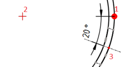
Ci sono alcune possibilità per creare una linea centrale per i fori. Prima si devono selezionare le linee o i punti sul foro come mostrato di seguito. Dopo, possono essere utilizzati i seguenti strumenti per creare la linea centrale:
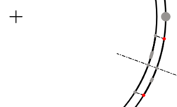
Above: created with which creates centerlines between 2 points
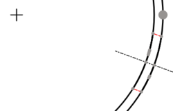
Above: created with which creates centerlines between 2 lines
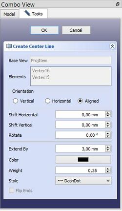
In the associated Combo View dialog box select in the Tasks panel under Orientation "Aligned" for axes out of main axes. Extend By means the length of the center line beyond of the body line in the drawing. With Shift Horizontal and Shift Vertical the center line can move in horizontal or vertical direction, if is necessary. Style means the figure of center line.

Above: dialog box
The created center line can change. Select the center line and press the button or
from the tool bar which you have created the center line. Delete the center line only with
from the tool bar after selecting the center line.
2. Setting angles:
Quadrant points select with from the tool bar. Next select the points as show below and use
from the tool bar to create the angle. Other succession create other angles.
Is there no catching point on the center line change "ISO count" in the properties.

Above: Succession of selection
- Pages: Insert Default Page, Insert Page using Template, Redraw Page, Print All Pages
- Views: Insert View, Insert Active View, Insert Projection Group, Insert Section View, Insert Complex Section View, Insert Detail View, Insert Draft Workbench Object, Insert Arch Workbench Object, Insert Spreadsheet View, Insert Clip Group, Share View, Project Shape
- Stacking: Move view to top of stack, Move view to bottom of stack, Move view up one level, Move view down one level
- Decorations: Hatch Face using Image File, Apply Geometric Hatch to Face, Insert SVG Symbol, Insert Bitmap Image, Turn View Frames On/Off
- Dimensions: Insert Length Dimension, Insert Horizontal Dimension, Insert Vertical Dimension, Insert Radius Dimension, Insert Diameter Dimension, Insert Angle Dimension, Insert 3-Point Angle Dimension, Insert Horizontal Extent Dimension, Insert Vertical Extent Dimension, Link Dimension to 3D Geometry, Insert Balloon Annotation, Insert Axonometric Length Dimension, Insert Landmark Dimension, Adjust Geometric References of Dimension
- Annotations: Insert Annotation, Add Leaderline to View, Insert Rich Text Annotation, Add Cosmetic Vertex, Add Midpoint Vertices, Add Quadrant Vertices, Add Centerline to Faces, Add Centerline between 2 Lines, Add Centerline between 2 Points, Add Cosmetic Line Through 2 points, Add Cosmetic Circle, Change Appearance of Lines, Show/Hide Invisible Edges, Add Welding Information to Leader, Add Surface Finish Symbol, Add Hole or Shaft Tolerances
- Extensions:
- Attributes and modifications: Select Line Attributes, Cascade Spacing and Delta Distance, Change Line Attributes, Extend Line, Shorten Line, Lock/Unlock View, Position Section View, Position Horizontal Chain Dimensions, Position Vertical Chain Dimensions, Position Oblique Chain Dimensions, Cascade Horizontal Dimensions, Cascade Vertical Dimensions, Cascade Oblique Dimensions, Calculate the area of selected faces, Calculate the arc length of selected edges, Customize format label
- Centerlines and threading: Add Circle Centerlines, Add Bolt Circle Centerlines, Add Cosmetic Thread Hole Side View, Add Cosmetic Thread Hole Bottom View, Add Cosmetic Thread Bolt Side View, Add Cosmetic Thread Bolt Bottom View, Add Cosmetic Intersection Vertex(es), Add an offset vertex, Add Cosmetic Circle, Add Cosmetic Arc, Add Cosmetic Circle 3 Points, Add Cosmetic Parallel Line, Add Cosmetic Perpendicular Line
- Dimensions: Create Horizontal Chain Dimensions, Create Vertical Chain Dimensions, Create Oblique Chain Dimensions, Create Horizontal Coordinate Dimensions, Create Vertical Coordinate Dimensions, Create Oblique Coordinate Dimensions, Create Horizontal Chamfer Dimension, Create Vertical Chamfer Dimension, Create Arc Length Dimension, Insert '⌀' Prefix, Insert '〼' Prefix, Remove Prefix, Increase Decimal Places, Decrease Decimal Places
- Export: Export Page as SVG, Export Page as DXF
- Additional: Line Groups, Templates, Hatching, Geometric dimensioning and tolerancing, Preferences
- Getting started
- Installation: Download, Windows, Linux, Mac, Additional components, Docker, AppImage, Ubuntu Snap
- Basics: About FreeCAD, Interface, Mouse navigation, Selection methods, Object name, Preferences, Workbenches, Document structure, Properties, Help FreeCAD, Donate
- Help: Tutorials, Video tutorials
- Workbenches: Std Base, Arch, Assembly, CAM, Draft, FEM, Inspection, Mesh, OpenSCAD, Part, PartDesign, Points, Reverse Engineering, Robot, Sketcher, Spreadsheet, Surface, TechDraw, Test Framework
- Hubs: User hub, Power users hub, Developer hub

