Arch CutLine: Difference between revisions
(The Arch CutLine tool allows you to cut a solid Arch object like an Arch Wall or Arch Structure using a line that is crossing the object.) |
(V0.22 -> V1.0) |
||
| (16 intermediate revisions by 5 users not shown) | |||
| Line 2: | Line 2: | ||
<translate> |
<translate> |
||
<!--T:1--> |
|||
{{docnav |
|||
{{Docnav |
|||
|[[Arch_Schedule|Schedule]] |
|||
| |
|||
|[[Arch_Add|Add component]] |
|||
| |
|||
|[[ |
|[[Arch_Workbench|Arch]] |
||
|IconL=Arch_Schedule.svg |
|||
|IconL= |
|||
|IconR= |
|||
|IconC=Workbench_Arch.svg |
|IconC=Workbench_Arch.svg |
||
|IconR=Arch_Add.svg |
|||
}} |
}} |
||
<!--T:11--> |
|||
{{VeryImportantMessage|THIS COMMAND IS OBSOLETE<br> |
|||
It is not be available in {{VersionPlus|1.0}}. Use [[Arch_CutPlane|Arch CutPlane]] instead.}} |
|||
<!--T:2--> |
|||
{{GuiCommand |
{{GuiCommand |
||
|Name=Arch CutLine |
|Name=Arch CutLine |
||
|MenuLocation=Arch → Cut with |
|MenuLocation=Arch → Cut with line |
||
|Workbenches=[[Arch_Workbench|Arch]] |
|Workbenches=[[Arch_Workbench|Arch]] |
||
| ⚫ | |||
|Version=0.19 |
|Version=0.19 |
||
| ⚫ | |||
}} |
}} |
||
==Description== |
==Description== <!--T:3--> |
||
<!--T:4--> |
|||
The |
The '''Arch CutLine''' tool cuts a solid Arch object like an [[Arch_Wall|Arch Wall]] or [[Arch_Structure|Arch Structure]] with a straight edge. Based on that edge and the normal of the [[Draft_SelectPlane|Draft working plane]] a cutting face is generated. |
||
</translate> |
|||
[[Image:Arch CutPlane example.jpg|640px]] |
|||
[[File:Arch_CutLine_example_1.png|x300px]] [[File:Arch_CutLine_example_2.png|x300px]] |
|||
<translate> |
|||
<!--T:5--> |
|||
{{Caption|[[Arch_Wall|Arch Wall]] cut by a line.}} |
|||
{{Caption|[[Arch_Wall|Arch Wall]] cut by a line. Left: subtractive box that appears when using the tool. Right: resulting wall after the cut is done.}} |
|||
==Usage== |
==Usage== <!--T:6--> |
||
<!--T:7--> |
|||
| ⚫ | |||
# If required align the working plane: |
|||
# Then select the edge to be used to cut the object, for example, a [[Draft_Wire|Draft Wire]]. This object should be selected in the [[3D_view|3D view]] only. |
|||
#* The selected edge may not be parallel to the normal of the working plane. |
|||
| ⚫ | |||
#* The generated cutting face will be perpendicular to the working plane. |
|||
| ⚫ | |||
| ⚫ | |||
| ⚫ | |||
# Select a straight edge. This must be selected in the [[3D_view|3D view]]. |
|||
| ⚫ | |||
| ⚫ | |||
| ⚫ | |||
==Scripting== |
==Scripting== <!--T:8--> |
||
<!--T:9--> |
|||
{{Emphasis|See also:}} [[ |
{{Emphasis|See also:}} [[Arch_API|Arch API]] and [[FreeCAD_Scripting_Basics|FreeCAD Scripting Basics]]. |
||
<!--T:10--> |
|||
{{Docnav |
|||
| |
|||
| |
|||
|[[Arch_Workbench|Arch]] |
|||
| |
|||
| |
|||
|IconC=Workbench_Arch.svg |
|||
}} |
|||
| ⚫ | |||
| ⚫ | |||
</translate> |
</translate> |
||
| ⚫ | |||
| ⚫ | |||
Latest revision as of 10:51, 21 April 2024
THIS COMMAND IS OBSOLETE
It is not be available in version 1.0 and above. Use Arch CutPlane instead.
It is not be available in version 1.0 and above. Use Arch CutPlane instead.
|
|
| Menu location |
|---|
| Arch → Cut with line |
| Workbenches |
| Arch |
| Default shortcut |
| None |
| Introduced in version |
| 0.19 |
| See also |
| Arch CutPlane |
Description
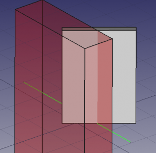
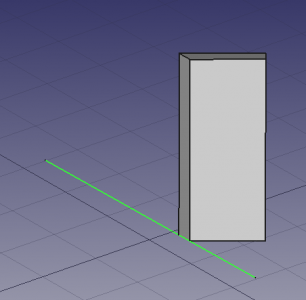
The Arch CutLine tool cuts a solid Arch object like an Arch Wall or Arch Structure with a straight edge. Based on that edge and the normal of the Draft working plane a cutting face is generated.
Arch Wall cut by a line. Left: subtractive box that appears when using the tool. Right: resulting wall after the cut is done.
Usage
- If required align the working plane:
- The selected edge may not be parallel to the normal of the working plane.
- The generated cutting face will be perpendicular to the working plane.
- Select the object to be cut in the Tree view or the 3D view.
- Select a straight edge. This must be selected in the 3D view.
- Press the
Cut with line button.
- Choose Behind or Front to indicate on which side of the cutting face material should be removed.
- Press the OK button.
Scripting
See also: Arch API and FreeCAD Scripting Basics.
- Elements: Wall, Structure, Curtain Wall, Window, Roof, Space, Stairs, Equipment, Frame, Fence, Truss, Profile, Pipe, Pipe Connector
- Reinforcements: Straight Rebar, U-Shape Rebar, L-Shape Rebar, Stirrup, Bent-Shape Rebar, Helical Rebar, Column Reinforcement, Beam Reinforcement, Slab Reinforcement, Footing Reinforcement, Custom Rebar
- Panels: Panel, Panel Cut, Panel Sheet, Nest
- Materials: Material, Multi-Material
- Organization: Building Part, Project, Site, Building, Level, External reference, Section Plane, Schedule
- Axes: Axis, Axes system, Grid
- Modification: Cut with plane, Add component, Remove component, Survey
- Utilities: Component, Clone component, Split Mesh, Mesh to Shape, Select non-manifold meshes, Remove Shape from Arch, Close Holes, Merge Walls, Check, Toggle IFC Brep flag, 3 Views from mesh, Create IFC spreadsheet, Toggle Subcomponents
- Additional: Preferences, Import Export Preferences (IFC, DAE, OBJ, JSON, 3DS, SHP), IfcOpenShell, IfcPlusPlus, Arch API
- Getting started
- Installation: Download, Windows, Linux, Mac, Additional components, Docker, AppImage, Ubuntu Snap
- Basics: About FreeCAD, Interface, Mouse navigation, Selection methods, Object name, Preferences, Workbenches, Document structure, Properties, Help FreeCAD, Donate
- Help: Tutorials, Video tutorials
- Workbenches: Std Base, Arch, Assembly, CAM, Draft, FEM, Inspection, Mesh, OpenSCAD, Part, PartDesign, Points, Reverse Engineering, Robot, Sketcher, Spreadsheet, Surface, TechDraw, Test Framework
- Hubs: User hub, Power users hub, Developer hub

