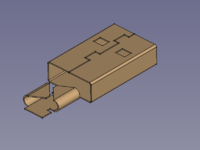
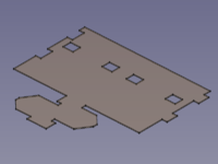
SheetMetal Examples
This documentation is not finished. Please help and contribute documentation.
GuiCommand model explains how commands should be documented. Browse Category:UnfinishedDocu to see more incomplete pages like this one. See Category:Command Reference for all commands.
See WikiPages to learn about editing the wiki pages, and go to Help FreeCAD to learn about other ways in which you can contribute.
Introduction
The SheetMetal workbench has grown quite powerful now and it demands an appropriate documentation.
To avoid the overcrowding of the tool pages with examples this page was added to collect parts showing and explaining special SheetMetal features.
Planned phases to generate content:
- Collecting pictures
- Adding workflow descriptions
- Adding more detailed tutorials
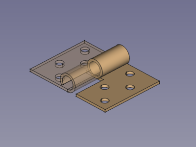
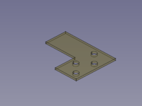
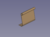
Hinge
Workflow Hinge:
Make Base Wall,
PartDesign Pocket,
PartDesign Hole,
Unfold.
Hinge Step by Step
- Create a profile, preferably using the
Sketcher Workbench. (A line and a tangent arc)
- Activate the
Make Base Wall command to create a BaseBend object.
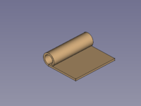
- Edit the BaseBend object's parameters:
- Set DataMid Plane to
trueto let the profile extend symmetrically to both sides of the sketch plane. - Set Dataradius and Datathickness to values of your choice.
- Set DataMid Plane to
- Create a cut-out contour, preferably using the
Sketcher Workbench.
- Use the
PartDesign Pocket command to cut off one half of the Round bit.
- Create a hole pattern, preferably using the
Sketcher Workbench.
- Use the
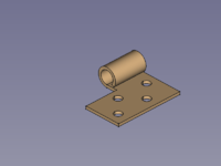
PartDesign Hole command. Avoid the countersink and counterbore options to keep the body unfoldable.
- Activate the
Unfold command to get an Unfold object.
- Done!
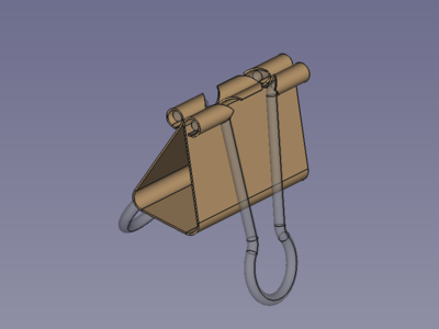
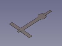
Paper Clip
Workflow Paper Clip:
Make Base Wall,
Sketch on Sheet,
clone, flip and fuse,
Unfold.
Paper Clip Step by Step
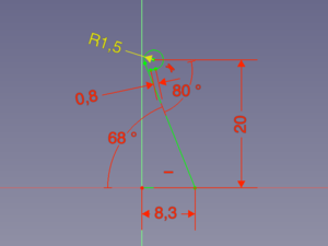
- Create a profile, preferably using the
Sketcher Workbench on the XZ plane.
- Activate the
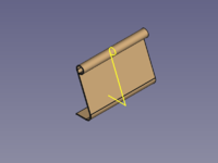
Make Base Wall command to create a BaseBend object.
- Edit the BaseBend object's parameters in the properties panel:
- Set DataMid Plane to
trueto let the profile extend symmetrically to both sides of the sketch plane. - Set Datalength to 32 mm.
- Set Dataradius to 2 mm.
- Set Datathickness to 0.3 mm.
- Set DataMid Plane to
- Select the face between the round sections and activate the
Sketcher Workbench.
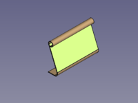
- To hide the curled part use the
Sketche View section command.
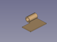
- Create the cut-out contour.
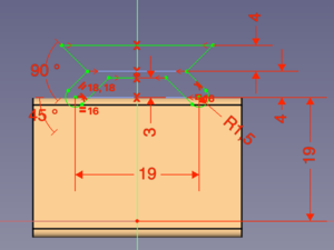
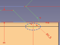
- Finish the sketch using the
Sketcher Leave sketch command.
- Select the face again and add the Cut-out sketch to the selection.
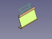
- Use the
Sketch on Sheet command to cut around the curled bit.
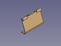
Now one side is finished and we need to find a way to mirror the body.
- The
PartDesign Mirrored command fails, because it can mirror features but not bodies and SheetMetal features seem to be not valid in this case.
- The
Part Mirror command creates a mirrored part, but this is no longer unfoldable.
- One way is to use clone. This still can't be mirrored, but it can use axial symmetry (turn it 180°).
- Another way is to use link objects.
The flip a clone way:
- Select the body from the tree view
- Use the
Create a clone command. It adds a new body containing a clone object.
To apply a 180° turn set the DataAngle under the Placement property of either the body or the clone to 180°. (Z axis is default and should be fine if you started on the XZ plane as described)

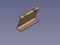
- With the body still active, use the
PartDesign Boolean operation command to add the body of the clone and finally to fuse both halves.
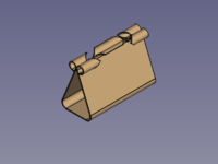
- Activate the
Unfold command to get an Unfold object.
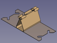
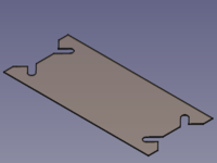
- Done!
The link objects way:
- Select the body from the tree view.
- Use the
Make link command. This adds a new link object.
- Duplicate the link object by setting the property DataElement Count to 2.
- To apply a 180° turn set the DataAngle under the Placement property of either of the sub-linked objects to 180°. (Z axis is default and should be fine if you started on the XZ plane as described)
- Select both sub-linked objects in the tree view.
- Activate the
Part Fuse command to fuse both halves.

- Activate the
Unfold command to get an Unfold object.


- Done!
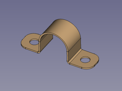
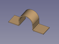
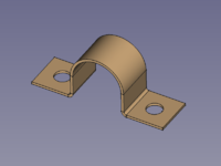
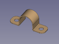
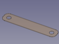
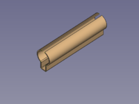
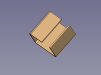
Omega Clamp
Workflow Omega Clip:
Make Base Wall,
PartDesign Hole,
PartDesign Fillet,
Unfold.
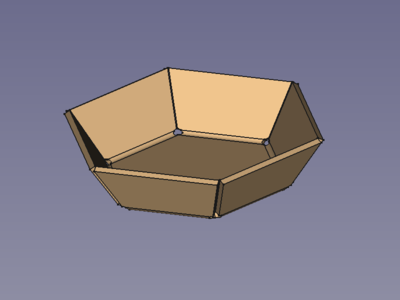
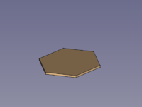
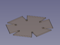
Hex Bowl
Workflow Hex Bowl:
Make Base Wall,
Make Wall,
6x
Add Corner Relief,
Unfold.
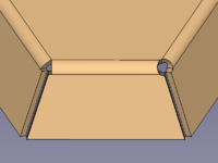
When a Corner Relief is added (right side) it can be necessary to adjust the value of the Size property.
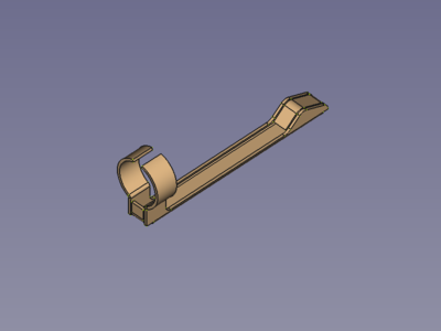
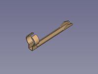
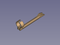
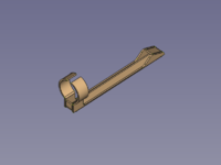
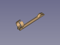
Pen Clip
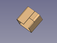
Workflow Pen Clip:
Make Base Wall,
PartDesign Pocket,
3x
Make Wall,
Unfold.
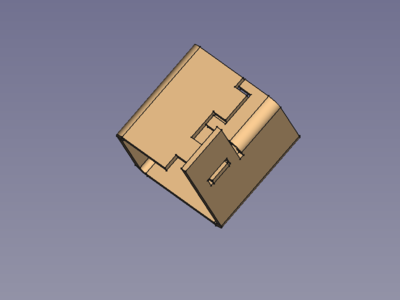
Extend Face Example
Workflow Extend Face Example:
Make Base Wall,
Make Wall,
Extend Face,
Extend Face,
Unfold.
For the second use of Extend Face a Sketch with two contours is used for shape of the extension(s); and with the value of "use subtraction" set to true it provides the shape for the cut-outs, as well
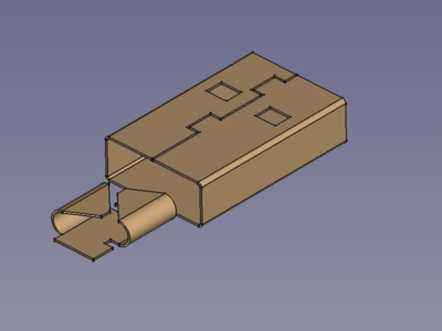
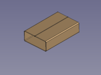
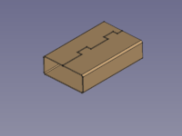
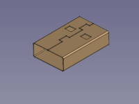
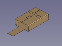
USB shield contact
Workflow USB shield contact:
Make Base Wall,
Extend Face,
PartDesign Pocket,
Extend Face,
Make Wall,
Unfold.
(The pull relief is just an artistic expression of what could be hidden inside a real plug)
